Tethered Satellite Propulsion
200 likes | 438 Views
Tethered Satellite Propulsion. Icarus Student Satellite. ProSEDS. Topics. What is Tethered Propulsion Why do we need Tethered Propulsion How do we implement the model for Tethered Propulsion. Why. Normal Satellite Missions Launch rocket/space shuttle

Tethered Satellite Propulsion
E N D
Presentation Transcript
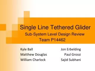
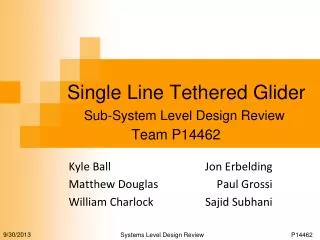
Tethered Satellite Propulsion Icarus Student Satellite ProSEDS
Topics • What is Tethered Propulsion • Why do we need Tethered Propulsion • How do we implement the model for Tethered Propulsion
Why • Normal Satellite Missions • Launch rocket/space shuttle • Shuttle deploys payload (usually satellite) • Satellite performs function, and then eventually loses enough momentum to fall out of orbit • If Satellite needs more time in space, fuel must be shipped up to the satellite • Bottom Line: needs fuel
Why • Disadvantages of Fuel: • Expensive • Refueling MIR space station costs estimated at about $1 billion. • Limited Supply • Earth is already running out of fossil fuels, nuclear/renewable resources not yet a viable solution for propulsion in space • We need a propellant-less propulsion model
How • Earth has magnetic field • Earth has electric field • Basic law of Physics : F = B x I • If we could utilize the Earth’s electric and magnetic fields by driving current in the right direction, then we can generate an electromotive force sufficient for use in orbit
How • Keep it simple: • Generate current along a straight line • Use a taut conducting wire (Tether) to channel the current • Tether needs to be kept taut and oriented properly in the magnetic field • Another basic rule of physics: if two masses connected by a tether are in orbit, the masses will align themselves along the local vertical regardless of the starting orientation.
What • ProSEDS – Propellant-less Small Expendable Deployer System • Drives current through the tether • Deploys endmass (Icarus) • Icarus (ProSEDS Endmass) • Dead weight (~20 kg +/- 0.4 kg) • Used to study tether physics • Possible backup in case of ProSEDS failure
Icarus Student Satellite • First (real) student built, designed, and tested satellite • Part of the tethered satellite propulsion model • Scheduled to be launched March/May 2001 • Advantageous since it is an instrumented endmass as opposed to a passive dead weight • Helps prove NASA’s “cheaper/faster/better” solution model
What • Payload • GPS, Magnetometer – provide location information • GPS unit uses the GPS satellite network • Magnetometer compares the magnetic readings at present location against the current model of the Earth’s magnetic field • Together, both units provide a complete measurement of the physics of the Endmass
What • Control and Data Handling Subsystems • Octagon systems 386 board assimilates the information, sends it to the transmitter Power: 3.0 W • Memory: 2.64 MB total • 2 MB DRAM • 512 kB FLASHROM • 128 kB SRAM (battery backed) • A/D: 8 channels, 12 bit accuracy • Serial Ports: 2 UART 16C550 chips with RS-232 voltage level • Digital I/O: 24 channels (TTL) • Operating Temperature: -40 to 85 C
What • Control and Data Handling Subsystems • Custom C&DH Board performs tasks required specifically by the Endmass • Analog MUX used to multiplex A/D channels – provides 23 total channels • Platform for Health Data Collection • Power and Data Connections for all Subsystems • 2 4-Orbit Timers in Series • 2 21-Day Timers in Parallel • GSE Data Connection • GPS Hard Reset Switch
What • Power and Electrical Subsystems • Power Distribution System • Solar Cells • Used to provide main power to the Endmass in day-side of the orbit (8 W) and to charge the batteries • Total power provided ~16 W • Batteries (Ni-Cd) • Used to provide main power to the Endmass in Eclipse (~8 W)
PAA (15pin) GSE (50pin) GPS Octagon Tx Mag Batt What Female on inside, male on outside from PAA switches Bulkhead Mounted Bulkhead Mounted Female on Icarus side, Male from GSE box 4 wires ~30” PAAGSE 25 wires ~25.5” 8 wires ~20.5” 12 wires ~38” Male connector on Mag ., so cable has female connector on this end. PEGSE CDHGSE 2+, 1- each string negatives connected on each panel, Tail,Top,PAA: 16.25”, Outboard 26.25”, Nose: 22.5”, Bottom: 24.3” Custom Transmitter Connector (REM- no toxic metals) CDHBatt PEPAA 7 wires, ~18” 2 wires ea ~7,17,17,32” CDHMag PESolar 25pin 9pin GSE(J1) Mag(J3) 4 wires ~6.5” Solar Cells(J1) 37pin 9pin Tx(J4) 37pin PE Therm(J5) CDH 9pin CDHTx PAA GSE(J2) CDHGPS 24 wires PE(J2) 4.1,4.2 GPS(J7) 25pin 9pin,9pin 15pin 15pin Battery(J3) CDH(J4) 14 wires ~9.5” Octagon(J6) 37pin 8 wire ~7” PEBattery 33 wires, ~6” 16 wires ~12”, 15” 8 go to 9 pin connector on PE, 8 go to floating connector. 2 wire Keepalive battery connected to CDH board via jumpers at GSE connector. 9pinmale 8 wires PECDH2 8 wires PECDH1 Male connector on GPS, so cable has female connector on this end. 2 Jumper wires go straight to Octagon board instead of through C&DH board. All wire is 24 guage, from the lab downstairs. (Flight qualified.)
What • Transmitter • Outputs assimilated data from the Octagon board @ ~2.247 GHz • Ground stations at various locations around the world are set up to receive the data from this transmitter • The data is then relayed back to the Icarus team for analysis and conclusions
Schematic Magnetometer C&DH System 3 Analog Values Sampled 1/sec Octagon 386 on/off A/D Dig I/O Digital bit stream Connection: TTL Health System MEM MUX Thermistors, Currents, Voltages Sampled 1/min data Transmitter Serial Port Serial Port Ground Support Equipment on/off GPS Development and Testing Connection: RS-232 Sampled 1/ 2 sec Connection: RS-232
System Level Diagram Power Path Data Path Solar Cells Control 2 8 bits Separation Switches PAA 4 orbit timer 21 day timer C&DH Payload Chip 25 MHz Telemetry Battery GPS Receiver Magnetometer ROM 512 kB Transmitter (2.2475 GHz) RAM 2 MB V = 5.0 V DCI = 185 mA V = 5.0 V DCI = 11 mA SRAM 128 kB V = 5.0 V DCI = 650 mA Power Distribution V = 12.0 VDCI = 400 mA GPS Almanac Data Tether attachment point tether ProSEDS U of M GSE
Mission Plan T=?Instrument Measurements T=+1 dayETDDeployment T=~3 hoursTether Deployment T=+60 min Power-up, Release T=21+ daysReentry T=0March/May 2001Delta-II Launch!