DriveWorks Xpress
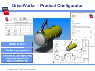
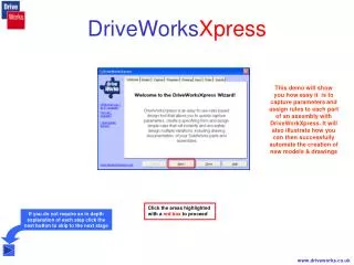
DriveWorks Xpress. This demo will show you how easy it is to capture parameters and assign rules to each part of an assembly with DriveWorkXpress. It will also illustrate how you can then successfully automate the creation of new models & drawings.

DriveWorks Xpress
E N D
Presentation Transcript
DriveWorksXpress This demo will show you how easy it is to capture parameters and assign rules to each part of an assembly with DriveWorkXpress. It will also illustrate how you can then successfully automate the creation of new models & drawings Click the areas highlighted with a red box to proceed If you do not require an in depth explanation of each step click the next button to skip to the next stage www.driveworks.co.uk
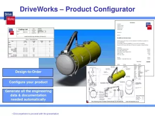
Models The first step of the wizard is to let DriveWorksXpress know which parts and sub-assemblies require automating • Place a tick in the box next to the models you require DriveWorksXpress to control If your assembly contains parts or sub-assemblies that never change they do not require to be selected In this example we are going to specify the new height & width of the gantry and see how other associated parameters are modified automatically as a result www.driveworks.co.uk
Capture The second step is to capture the parameters of each model that change Parameters can be sketch or feature dimensions, features, offset or angular planes or distance and angular mates • Highlight any part or sub-assembly that contains the parameters to be captured Once selected from the tree in the wizard the model automatically opens in the SolidWorks window www.driveworks.co.uk
Capture - Top Half of Leg Length • From the feature manager, select the feature that contains the dimension to be captured (This model is extruded up to a plane so we will capture the plane named Bottom). • Select the dimension that appears on the model. • The SolidWorks name appears in the DriveWorksXpress window. • Give this dimension a more meaningful name and click Add. • Select the next model from the tree in the DriveWorksXpress window that requires parameters capturing. www.driveworks.co.uk
Capture - Base of Lower Leg Length • From the feature manager, select the feature that contains the dimension to be captured (The Length of the part exists in the Base-Extrude-Thin feature). • Select the dimension that appears on the model. • The SolidWorks name appears in the DriveWorksXpress window. • Give this dimension a more meaningful name and click Add. • Select the next model from the tree in the DriveWorksXpress window that requires parameters capturing. www.driveworks.co.uk
Capture - Beam Length • From the feature manager, select the feature that contains the dimension to be captured (The Length of the part exists in the Base-Extrude feature). • Select the dimension that appears on the model. • The SolidWorks name appears in the DriveWorksXpress window. • Give this dimension a more meaningful name and click Add. • Select the next model from the tree in the DriveWorksXpress window that requires parameters capturing. www.driveworks.co.uk
Capture - Beam Assembly right hand upright left hand upright • From the feature manager, select the plane that contains the dimension to be captured (The Right Hand Upright Plane). • From the feature manager, select the plane that contains the next dimension to be captured (The Left Hand Upright Plane). • Select the dimension that appears on the model. • Select the dimension that appears on the model. • The SolidWorks name appears in the DriveWorksXpress window. • The SolidWorks name appears in the DriveWorksXpress window. • Give this dimension a more meaningful name and click Add. • Give this dimension a more meaningful name and click Add. • Click Next in the DriveWorksXpress Wizard www.driveworks.co.uk
Custom Properties Custom Properties can be used to report data into the model These in turn can be reported into a SolidWorks drawing and used to populate drawing border title blocks, notes and other important drawing information automatically The Properties tab in the DriveWorksXpress wizard automatically reports any custom properties that currently exist in the model Additional custom properties can be added Unwanted custom properties can be deleted www.driveworks.co.uk
Drawing The next step is to tell DriveWorksXpress that a new drawing is needed Select the drawing that the new file will be based on The new drawing will reflect all the newly created data with all dimensional information, bill of materials, custom properties etc. automatically updated Click Browse to select your drawing Locate the drawing and click Open www.driveworks.co.uk
Input Order Number The next step is to create a customised form for specifying the new models Define the criteria required to specify the new models eg.dimensions, materials, finishes and even sales order number Enter the name for the Input control A control that defines the order number will allow us to assign a rule to the naming of each file that will identify each new model to be created. This could just as easily be a naming convention that is made up of all the variables that define the new model. Select the type of control required The Required field, when selected, allocates a control as a mandatory field. Click Apply to register the control www.driveworks.co.uk
Input Drawn By Glen David Maria All other controls are added with the same ease. Click Add to specify another control The next control will report data regarding the person specifying the new models into the Drawn By custom property – which in turn will reflect through to the new finished drawing. The name of the control is entered and the type selected. Values are entered that will appear in the drop down control. Click Add to register each value. Click Apply to register the control www.driveworks.co.uk
Input Safe Working Load Outside Outrigger Width between Legs Inside Outrigger Height to Underside of Material Finish 500 2000 100 3800 2000 5000 1000 Options include spin buttons, text boxes, drop downs and check boxes Other Input controls required to specify our new model include… A Spin Button to specify the Safe Working Load A Text Box to specify the Height A Text Box to specify the Width A Drop Down to specify the Material A Drop Down to specify the Finish A Check Box to specify if an Inside Outrigger is required A Check Box to specify if an Outside Outrigger is required www.driveworks.co.uk
Rules The Rules tab shows all the parameters that require Rules associating to them. These are highlighted RED www.driveworks.co.uk
Rules 1. Select a parameter to add a rule. 2. Select a variable to use in the rule. Either double click or drag and drop the variable into the ‘Build up’ box. As the Safe Working Load Custom Property equals The Safe Working Load Input Variable the rule has now been satisfied. 3. Hit Apply. 4. Repeat for the other parameters who’s values come directly from an Input. www.driveworks.co.uk
Rules A rule to determine if the Outrigger Assembly file is required The Outrigger Assembly Outside File Name is selected Click the IF rule The IF rule can now be built up exactly as done using Microsoft Excel • The IF rule will verify that the Outside Outrigger check box from the Input form has been selected. • When this check box = “Yes” DriveWorksXpress will create a new file with the Order_Number as a suffix to the file name. • When this check box does not = “Yes” DriveWorksXpress will “Delete” this file from the assembly. • Click here A similar rule will apply to the File Name of the Outrigger Assembly. NEXT…… www.driveworks.co.uk
Rules The remaining File Names will use the order number Input as a suffix to the naming of each new file. All parts and sub-assemblies with the File Name parameter type are multi-selected. The Order Number Input Variable is selected Click Apply NEXT…… www.driveworks.co.uk
Rules • The Length dimension of the top half of leg is calculated from the Height to Underside of Beam Input – a constant value of 300mm • The Length dimension of the Beam can be the Width between Legs Input + 920mm or Width between Legs Input + 160mm dependant on The Outside Outrigger check box being selected • The Length dimension of the base of lower leg is dependant on the Height to Underside of Beam Input. Less than 2700 = 1550, Less than 3800 = 1775 or Over 3800 = 2000. This is formulated by nesting a series of IF statements together • The Left and Right hand upright distance dimension of the Beam Assembly are dependant on the Outside Outrigger Input being selected. If “Yes” = 460 otherwise = 80 • The Drawing Number Custom Property is constructed by joining the Order Number Input with the text string “/GA/01” • The Description Custom Property will report the Safe Working Load Input • The Title Custom Property will be a text string produced from a constant value of “Gantry” joined with the Width between Legs Input and the Height to underside of Beam Input. Where we require a standard text string of “Wide” and “Height” included after the respective size this is selected from the drop down box as shown. All remaining unspecified rules are constructed either by using the available icons or, if familiar with Microsoft Excel, typing direct into the Build Up box Each rule will reference Variables from the Inputs or Outputs or have constant data attributed to them www.driveworks.co.uk
Rules Once all of the Rules have been satisfied the Rules tab on the DriveWorksXpress wizard appears with each output variable ticked. www.driveworks.co.uk
Specify ON1004 Glen 3565 2706 Steel Once the specify tab is selected DriveWorksXpress will automatically create the user form from the information added at the Input stage of the wizard The form can now be populated with the requirements of the new set of models required to be produced. If values are entered that are outside the minimum and maximum values set at the Input stage DriveWorksXpress will not let you continue. www.driveworks.co.uk
End Result All the rules and parameters are stored in a database created by DriveWorksXpress. Each time a new variant is required DriveWorksXpress will automatically load the previously captured data. www.driveworks.co.uk
Further Information For further information on DriveWorks and DriveWorksXpress visit www.driveworks.co.uk