Download
1 / 12
140 likes | 323 Views
Emission Control. Topics covered in this presentation: Types of Emissions Emission Control Devices. Emission Types.

E N D
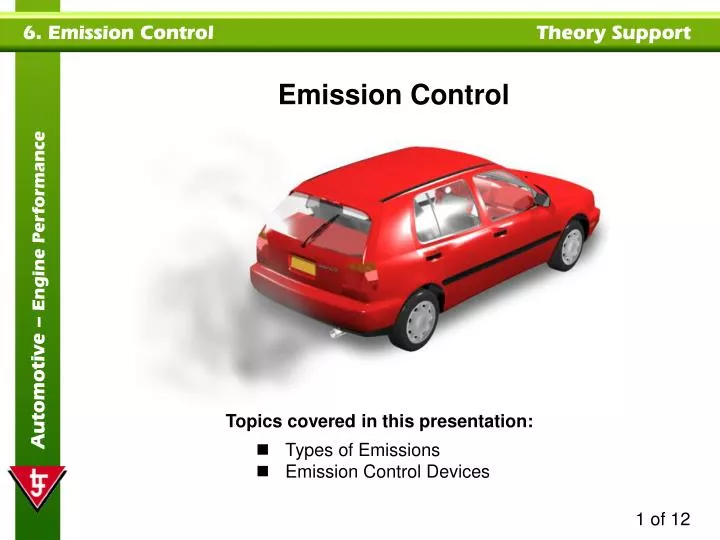
Emission Control • Topics covered in this presentation: • Types of Emissions • Emission Control Devices
Emission Types Vehicles are responsible for producing emissions that are harmful to the atmosphere and the environment. Legislation has been introduced stating that emissions must be reduced. The major emissions produced by a vehicle are: • Hydrocarbons (HC) are created by unburned fuel entering the atmosphere. They are either fuel that has not combusted properly or fuel vapor leaking from the fuel bowl, filler pipe etc. HCs are reactive and can cause illnesses. • Oxides of Nitrogen (NOX) are formed when nitrogen and oxygen mix under high pressure and high temperature (25000F). NOX can cause eye and respiratory problems.
Emission Types • Carbon Monoxide (CO) is caused by the incomplete combustion of fuel. It is an invisible poisonous gas that can be fatal if large amounts are inhaled. • Particulates are soot particles caused by fuel additives. They are particularly prominent with diesel engines. 30% of the particles sink to the ground while the other 70% can be airborne for long periods of time.
Emission Control Systems Modern vehicles are fitted with emission control systems, designed to reduce emissions. These include: • A catalytic converter. • Air injection (AIR) system. • Exhaust gas recirculation (EGR) system. • Evaporative emissions control (EVAP) system. • Positive crankcase ventilation (PCV) system.
Catalytic Converter A catalytic converter removes the harmful gases that exit the tailpipe. A three-way converter contains honeycomb coated with platinum, palladium and rhodium to form oxidization and reduction converters. The oxidization converter stores oxygen when the air/fuel mixture is lean. It converts hydrocarbons (HC) into water (H2O) and carbon monoxide (CO) into carbon dioxide (CO2). Catalyst honeycomb The reduction converter converts oxides of nitrogen (NOX) into nitrogen (N2) and oxygen (O2). Outlet Inlet The conversion process produces temperatures upto 1600°F. Oxidization converter Reduction converter Steel shell
Air Injection System This system forces clean air into exhaust ports to ignite unburned fuel (hydrocarbons), within the exhaust manifold. Some systems also force air into a catalytic converter to aid the conversion process. Air is forced into the exhaust ports by a vane type air pump, via an air injection manifold. Vacuum operated diverter valve is used to stop air flow during deceleration, otherwise backfiring may occur within the exhaust. A check valve is placed in the line to stop hot exhaust gases traveling back up the air hose.
EGR valve Ported vacuum Throttle plate TVV Exhaust gas flow Intake manifold Exhaust Gas Recirculation (EGR) System The EGR system reduces NOX emissions. It feeds inert exhaust gases back into the intake manifold, where they dilute the air/fuel mixture, without altering the air/fuel ratio. With less oxygen and fuel, combustion temperatures (and therefore NOx levels) are lower. The system uses an EGR valve that can be either vacuum and/or electronically controlled. Early EGR valves were operated by ported vacuum. They did not function until engine was at operating temperature and above idle speed.
Pressure voltage signals EVR duty cycle control signal ECU Vacuum output Intake vacuum DPFE sensor EVR EGR valve EGR flow Intake manifold Metering orifice Exhaust pressure Exhaust gas Electronic EGR Components In an electronic system, the ECU uses data from sensors to control EGR valve operation. The ECU calculates the ideal quantity of exhaust gas to recirculate (and timing). This provides optimum vehicle efficiency with the least amount of emissions. Vehicles that conform to OBD II regulations must be fitted with feedback sensors (DPFE) to confirm valve operation.
Air dome Fuel outlet High pressure release Cap Vent line Electronic Evaporative Emissions Control Fuel produces vapors, if stored in a container that contains air. The rate at which fuel vapor is produced increases with air temperature increase. Older vehicles had vented fuel tanks and carburetors, allowing fuel vapors to enter the atmosphere. In a modern vehicle, the fuel system is sealed and fuel vapors are stored and then burned at an appropriate time, along with the normal air/fuel mixture. The fuel tank has a sealed cap that may contain valves to relieve fuel pressure and allow air in. The tank contains an air dome that allows for fuel expansion and a vent line for vapor removal.
Vacuum line Roll over valve/vapor separator Throttle plate Purge valve Non-vented cap Vent line Intake manifold Purge line Air Fuel vapour Fuel tank Charcoal canister Vacuum Electronic Evaporative Emissions Control The vent line is fitted with a roll over/vapor separator valve to stop liquid fuel entering the system (vehicle inversion). It connects to a charcoal canister that stores vapors when the engine is switched off. A purge valve is used to control vapor removal from the canister. Vapors are drawn into the intake manifold via a purge line. On older vehicles the valve is operated by ported vacuum (shown). On modern engines, the ECU controls valve operation for optimum engine efficiency.
Fresh air enters through the air cleaner Vapors pass into the intake manifold Air flow Vapors pass through the PCV valve and hose Blowby Fresh air mixes with blowby gases in the crankcase Positive Crankshaft Ventilation (PCV) Combustion produces high pressure in a cylinder. Some of the pressurized gas leaks past the piston rings into the crankcase, even on a new engine and is known as 'blowby'. Older vehicles had a breather tube that vented these gases into the atmosphere. Modern vehicles are fitted with a PCV system. Vacuum is used to suck blowby out of the crankcase and into the intake manifold to be burned. Fresh air replaces the gases in the crankcase. System operation is regulated by a PCV valve.
= Vapor PCV Valve The PCV valve is a spring-loaded device, with an engine specific orifice size. The valve is sealed shut when an engine is stopped to prevent backfires. Spring To manifold From crankcase Seal seat At engine idle speed, maximum vacuum defeats spring pressure and the plunger moves to the other end of the valve, allowing minimal vapor flow. Valve At normal engine speeds, lower vacuum levels allow the plunger to move to a central position and maximum vapor flow occurs.