Comprehensive Overview of 741 Op-Amp Circuit Configurations with Positive Power Supply
150 likes | 290 Views
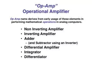
This guide provides a detailed exploration of various circuit configurations using the 741 operational amplifier. Featuring a positive power supply of +12V and a negative power supply of -12V, it covers inverting and non-inverting amplifier setups, summing amplifiers, buffered potentiometers, integrating amplifiers, and instrumentation amplifiers. Each configuration is illustrated with electrical schematics, showing input and output relationships, resistors, and power supplies. Ideal for electronics enthusiasts and professionals seeking to understand op-amp usage and applications.

Comprehensive Overview of 741 Op-Amp Circuit Configurations with Positive Power Supply
E N D
Presentation Transcript
Operational Amplifier (op-amp) Positive power supply (+12V) 8 1 Inverting - Positive power input (V-) 2 7 Inverting input Output (Vo) supply (+12V) 741 3 6 Non-inverting input Output Non-inverting + input (V+) 4 5 Negative power supply (-12V) Negative power supply (-12V) Integrated Circuit 8 Pin DIP (Dual In-line Package) Electrical Schematic Symbol
Single Input, Inverting amp i1 R1 R2 i2 + i- +12V Ei - + - E* - + + -12V Eo R3 -
Single Input, Inverting amp R1 R2 + +12V Ei - - + + -12V Eo R3 -
Multiple input, summing amplifier R3 R1 + R2 +12V E1 - + - + E2 + -12V Eo - R4 -
Single input, non-inverting amplifier R2 R1 +12V - R3 + + -12V + Eo Ei - -
Dual input, difference amplifier R1 R2 + +12V E1 - - R1 + + -12V + Eo E2 R2 - -
“Buffered” Potentiometer via Voltage Divider +12V +12V - + + + -12V EO Ei - - -12V
Integrating amp R C + +12V Ei - - + + -12V Eo -
Comparator +12V - + + Eref + -12V + Eo - Ei - -
Instrumentation Amp + R2 + - R1 R3 Ei - RG + + R3 R1 EO R2 - - - - +
+12V Function Generator DMM 7 +12V 2 - 741 4.237 6 + + 3 + VWHz Ein COM -12V 4 Eout - - COM -12V
+ Ein - 7 7 7 7 +12V +12V +12V +12V 2 2 2 2 - - - - 741 741 741 741 6 6 6 6 3 3 3 3 + + + + -12V -12V -12V -12V 4 4 4 4