Download

1 / 11
110 likes | 245 Views
Simple CFD Estimate of End Flange Tuner Finger Cooling. Estimated Dimensions. 6mm. 5cm. 1cm. 1cm. 3cm. 2cm. 4cm. 5cm. Estimated Heat Load. IPHI RFQ end flange: 26 Wcm -2 on fingers

E N D
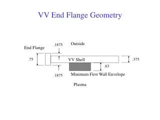
Estimated Dimensions 6mm 5cm 1cm 1cm 3cm 2cm 4cm 5cm
Estimated Heat Load IPHI RFQ end flange: 26 Wcm-2 on fingers (CW RFQ, though, so ours will have much less than this in reality, but 25 Wcm-2 will allow large safety margin) FETS RFQ: 62 Wcm-2 at vane cut-back Assume less than half this on fingers? So 25 Wcm-2 is reasonable.
Water out with temperature raised and at 0 Bar relative pressure Copper starting temperature = 22°C High mesh density in region between finger and pipe 15°C Water in at 1 ms-1 flow rate 25 Wcm-2 heat flux load on finger
Flow Estimates Total power, P, to be removed from each finger ≈ 160 W Water mass flow rate, , per pipe = 0.028 kgs-1 (assuming flow speed = 1 ms-1 = 1.7 l min-1) Estimated temperature rise, ΔT, of cooling water = 1.35 °C Pipe length, L, within copper = 10 cm Average water flow rate vav = 1 ms-1 Pipe diameter, DH = 6 mm Estimated pressure drop, Δp = 0.003 Bar Nusselt number, Nu, of water flow = 55.03 Thermal conductivity of water, k = 0.6 Wm-1K-1 Estimated heat transfer coefficient = 5500 Wm-2K-1
Faster, disrupted flow round corner increases local HTC Average HTC ~ 6000 Wm-2K-1 which agrees with estimate
Pressure drop is slightly higher than estimate because the pipe doesn’t have a smooth bend at corner, but it’s still nice and low
Bulk copper in end flange is ~ 40 °C Finger gets pretty warm (100 °C) but that shouldn’t matter at all
Summary • Majority of heat removed ok • Indirect cooling means finger gets hot • …but not enough to worry about • Assumes 25 Wcm-2 heat load (OVERESTIMATE!) • Will proceed with RF simulation to get better estimate of heat load on fingers • Overall, this cooling strategy should be fine