Plasma Vessel Shell Measurement Protocol for VVSA2 End Flange Geometry Verification
70 likes | 158 Views
This protocol ensures the proper fit of plasma vessel components by measuring end flange geometry and shell dimensions. Learn how to detect encroachments and maintain minimum clearance requirements.

Plasma Vessel Shell Measurement Protocol for VVSA2 End Flange Geometry Verification
E N D
Presentation Transcript
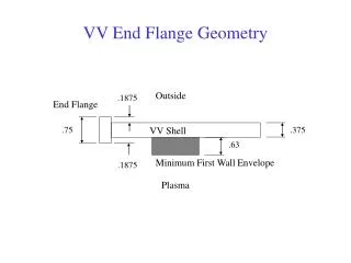
Outside .1875 End Flange .75 VV Shell .375 .63 Minimum First Wall Envelope .1875 Plasma VV End Flange Geometry
+ + + Outside .1875 End Flange .75 VV Shell .375 .63 Minimum First Wall Envelope .1875 Plasma VV End Flange GeometryMeasurement Sign Convention +
VVSA2 B End Points Out of Tolerance Flange In Flange Out Shell In Shell Out Sphere Radii are Minimum Clearance Required to FW. Any encroachment would show as penetrating FW
VVSA2 B End Points Out of Tolerance Flange In Flange Out Shell In Shell Out
VVSA2 A End Points Out of Tolerance Flange In Flange Out Shell In Shell Out
VVSA2 A End Points Out of Tolerance Flange In Flange Out Shell In Shell Out No Encroachment on FW