Fairness and Load Balancing in Wireless LANs Using Association Control
530 likes | 779 Views
IEEE/ACM TRANSACTIONS ON NETWORKING, VOL. 15, NO. 3, JUNE 2007. Fairness and Load Balancing in Wireless LANs Using Association Control. Yigal Bejerano, Member, IEEE, Seung-Jae Han, Member, IEEE, and Li (Erran) Li, Member, IEEE. Presented by 范姜竣韋 (C.W. Fan-Chiang) 許宴毅 (Y.Y. Hsu). 5. 1. 6.

Fairness and Load Balancing in Wireless LANs Using Association Control
E N D
Presentation Transcript
IEEE/ACM TRANSACTIONS ON NETWORKING, VOL. 15, NO. 3, JUNE 2007 Fairness and Load Balancing in Wireless LANs Using Association Control Yigal Bejerano, Member, IEEE, Seung-Jae Han, Member, IEEE, and Li (Erran) Li, Member, IEEE Presented by 范姜竣韋(C.W. Fan-Chiang) 許宴毅(Y.Y. Hsu)
5 1 6 3 4 2 7 INTRODUCTION SIMULATION RESULTS FAIRNESS AND LOAD BALANCING ASSOCIATION CONTROL ALGORITHMS ONLINE INTEGRAL-ASSOCIATION SYSTEM DESCRIPTION CONCLUSION Contents
5 1 6 3 4 2 7 INTRODUCTION SIMULATION RESULTS FAIRNESS AND LOAD BALANCING ASSOCIATION CONTROL ALGORITHMS ONLINE INTEGRAL-ASSOCIATION SYSTEM DESCRIPTION CONCLUSION Contents
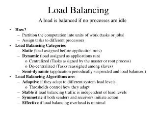
Introduction • Load imbalance • Each user associate itself with the AP that has the strongest RSSI(received signal strength indicator), while ignoring its load condition • Some APs may idle • Solution • Association control: • Balance the load via intelligently selecting the user-AP association
Introduction(cont’d) • Association control can be used to achieve different objectives. • To maximize the overall system throughput by shifting not from the fairness viewpoint • More desirable goal:provide fair bandwidth allocation, while maximizing the minimal fair share of each user • In this paper, we present efficient algorithms • Ensure max-min fair bandwidth allocation • This goal obtained by balancing the load on the APs
5 1 6 3 4 2 7 INTRODUCTION SIMULATION RESULTS FAIRNESS AND LOAD BALANCING ASSOCIATION CONTROL ALGORITHMS ONLINE INTEGRAL-ASSOCIATION SYSTEM DESCRIPTION CONCLUSION Contents
The Network Model • Assume that adjacent APs use noninterfering channels • Consider long-term fairness • Greedy users that always have traffic • consume all the allocated bandwidth
System Discription • System requires relevant information on each user, such as and • It needs an algorithm to determine the user-AP association • It need a mechanism to enforce these association decisions • the collected information is reported to a network operation center(NOC) • Periodically recalculates the optimal user association by using the offline algorithms
Periodic Offline Optimization • Motivation: • By showing the weakness of the existing heuristic load balancing mechanisms • Example: (b):Least-loaded-first(LLF) Bandwidth:{4/3, 1, 4/3} b/4+b/2=1b=4/3 (c)、(d):strongest-signal-first(SSF) Case1Bandwidth:{8/7, 8/7, 8/7} Case2Bandwidth:{8/3, 8/3, 2}
Wireless and Wired Bottlenecks • Wireless link is generally considered as the bottleneck this assumption is not always valid • Case I: • fair user association only from the wireless perspective • wireless: 0.5Mb/s to each user • T1 line: • APa: 0.5 Mb/s to user 5, 6 • Wireless link is the bottleneck • AP b: 3/8 to its associated user • Wired link is the bottleneck • Case II: • A fair user association • 0.5 Mb/s to each user over the wired and wireless channels
5 1 6 3 4 2 7 INTRODUCTION SIMULATION RESULTS FAIRNESS AND LOAD BALANCING ASSOCIATION CONTROL ALGORITHMS ONLINE INTEGRAL-ASSOCIATION SYSTEM DESCRIPTION CONCLUSION Contents
FAIRNESS AND LOAD BALANCING • Two association models • Single-association model=integral-association • Multiple-association model=fractional-association Its bandwidth allocation is the aggregated bandwidth • Denote by all the users that associated with AP a A • denotes the set of APs that u U is associated with.
A. Max-Min Fairness • A bandwidth allocation is a matrix • :aggregated bandwidth to user • Normalized bandwidth(NB): • NBV: sorted in increasing order • AP a is required to serve user u a period of over the wireless channeland over the infrastructure link • If a bandwidth allocation is feasible if and • Fair service:all users have the same allocated bandwidth the degree of fairness may cause reduction of the throughputprovide max-min fairness
A. Max-Min Fairness(cont’d) • max-min fairness • No way to increase the bandwidth of a user without decreasing the bandwidth of another user with the same or less normalized bandwidth • a user association is termed max-min fair if its correspondingbandwidth allocation is max-min fair B1={1,1,2,2,3} B2={1,1,1,1,2}
Example (b):‧a feasible fair association ‧every user receive b=1 (c):‧NBV={1,1,1,2,2} (d):‧NBV={1,4/3,4/3,4/3,4/3} • NBV of a fractional max-minfairness allocation alwaysNBV of the integral max-minfairness allocation • The users can be divided into fairness groups consists of all users that experience the same NB allocation 1 4/3 > =
B. Min-Max Load Balancing • The notion of load is not well defined • Neither # of users associated with an AP nor its throughput reflect the AP’s load • the load of an AP needs to reflect its inability to satisfy the requirements of its associated users and as such it should be inversely proportional to the average bandwidth that they experience • We are able to extend existing load balancing techniques to balance the AP loads and obtain a fair service
B. Min-Max Load Balancing(cont’d) • A fractional association is a matrixfor each u U, holds. • Each specifies the fractional association of user u with AP a. Reflects the fraction of user u’s total flow that it expects to get from AP a • A fractional association is feasible if • User produces a load of on the wireless channel of AP and a load of on its backhaul link
B. Min-Max Load Balancing(cont’d) • We define the load induced by user on AP to be thetime that is required of AP to provide usera traffic volumeof size
B. Min-Max Load Balancing(cont’d) • Define the load vector of an association matrix sorted in decreasing order
Example ¼+¼=1/2 ¼+¼+¼=3/4 ½+½=1 1 1 ¼+½=3/4 • (c):(integral) • ={1,1,1/2} • (d):(fractional) • ={1,3/4,3/4} • APs can be partitioned into load groups contains all the APs with the same load assigned in decreasing order. 1 2 2 1 4/3 4/3 4/3 1 1 4/3 1 3/4
B. Min-Max Load Balancing(cont’d) =1 normalize 1
B. Min-Max Load Balancing(cont’d) • In the following we refer to the load group of the most loaded APs and the corresponding fairness group as the bottleneck groups
B. Min-Max Load Balancing(cont’d) • Unfortunately, Theorem 5 is not satisfied in the case of a single association • Example: ={1,1,1/2} ={1,1,1,2,2} ={1,1,1,1,2}
5 1 6 3 4 2 7 INTRODUCTION SIMULATION RESULTS FAIRNESS AND LOAD BALANCING ASSOCIATION CONTROL ALGORITHMS ONLINE INTEGRAL-ASSOCIATION SYSTEM DESCRIPTION CONCLUSION Contents
ASSOCIATION CONTROL ALGORITHMS • Aextension of the scheduling unrelated parallel machines problem • For any ε< ½,there’s NO polynomial-time ( 1+ε ) approximation algorithm exists, unless P = NP • To seek for a complete min-max load balanced association. • A 2-approximation algorithm for unweighted users, • A 3-approximation algorithm for weighted users • An optimal solution for fair time allocation.
A. ρ*-Approximation With Threshold • Intuitively, we would like to guarantee to each user a bandwidth of at least 1/ ρ of the bandwidth that it receives in the optimal integral solution, for a constant ρ≧1. • However, there is neither upper nor lower constant bounds for the ratio .
A. ρ*-Approximation With Threshold (cont’d) • Our practical goal is to reduce the load of highly loaded APs, there is no need to balance the load of APs with load below a certain threshold T, where T is the maximal load that a user may generate on an AP as formulated in • Recall that T is indeed a very small value and in practical 802.11 networks T ≦1 s/Mb.
B. Scheme Overview • Integral Load Balancing Algorithm.
B. Scheme Overview (cont’d) • we utilize a linear program, denoted as LP1 which calculates a feasible association and also minimizes the maximal load on all the APs over both their wireless and wired channels
B. Scheme Overview (cont’d) • Bottleneck-group Detection Routine
2) The Rounding Method abc 1/2 1/2 1/2 1/2 1/2 1/2 Qa,1={1} 1/2 1/2 Qb,1={4,3} Qb,2={3,2} Qb,3={2} Qc,1={5,4} Qc,2={5}
E. Time Fairness(cont’d) 1/3 1/2
5 1 6 3 4 2 7 INTRODUCTION SIMULATION RESULTS FAIRNESS AND LOAD BALANCING ASSOCIATION CONTROL ALGORITHMS ONLINE INTEGRAL-ASSOCIATION SYSTEM DESCRIPTION CONCLUSION Contents
5 1 6 3 4 2 7 INTRODUCTION SIMULATION RESULTS FAIRNESS AND LOAD BALANCING ASSOCIATION CONTROL ALGORITHMS ONLINE INTEGRAL-ASSOCIATION SYSTEM DESCRIPTION CONCLUSION Contents
VI. SIMULATION RESULTS • Assume • Maximum transmission range: 150m • 20 APs are located on 5 by 4 grid • Number of users is either 100 or 250 • Users are randomly positioned in a circle-shaped hot spot with 150m near the center of the simulation network • Results are obtained from averaging 100 runs