Download
1 / 24
300 likes | 572 Views
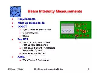
Beam Species Measurements on the MAST NBI system. Brendan Crowley Thanks to R King (CCFE) and A Bharatti (IPR). Outline of discussion. Neutral beams at MAST Ion Source Configurations Beam Species Model Beam Spectroscopy Results. Neutral Beams at MAST. Two on axis beams

E N D
CCFE is the fusion research arm of the United Kingdom Atomic Energy Authority Beam Species Measurements on the MAST NBI system Brendan Crowley Thanks to R King (CCFE) and A Bharatti (IPR)
Outline of discussion • Neutral beams at MAST • Ion Source Configurations • Beam Species Model • Beam Spectroscopy • Results
Neutral Beams at MAST • Two on axis beams • 75 keV 65 amps (D2) • Up to 2.5 MW NBI per beam • JET PINI type ion sources • Getter pumped beam boxes • The basis for several diagnostics • CXRS • MSE • FIDA
Neutral Beams at MAST • Two on axis beams • 75 keV 65 amps (D2) • Up to 2.5 MW NBI per beam • JET PINI type ion sources • Getter pumped beam boxes • The basis for several diagnostics • CXRS • MSE • FIDA
Neutral beams are used for: • Heating • Fuelling • Diagnostics (e.g. MSE, CXRS,FIDA) • Current drive • Rotation drive How well they do this depends on: • Beam penetration depth (particle energy) • Beam particle density • Beam current • Beam divergence (angular width) Mostly we need to know: • how much energy is deposited and • where it gets deposited…
Ion Sources Filament or RF driven discharge Magnetic confinement achieved by using permanent magnets in multi-cusp configuration - strong field on the walls, field-free region in the centre of the source. Ions created in various electron-molecule and ion-molecule collisions. Typical ion source parameters: • Primary electron energy (Varc): ~100eV • Arc current: <1500 A • Gas flow: 10 -15 mbar×l/s • Gas pressure: ~ 10-3 mbar Parameters determined by the ion source (fixed magnetic configuration and gas flow): • Arc efficiency: Ibeam/Iarc • Ion species fractions: H+:H2+:H3+
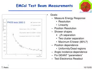
MAST NBI Ion Source • MAST injectors have ion sources with a supercusp magnetic filter field that is used to enhance the production of monatomic ions • No primaries are available for further ionisation of the neutral source gas. • The molecular ions are preferentially removed at low electron energies by dissociative attachment. Magnetic configuration of the standard MAST supercusp ion source.
MAST NBI Ion Source • Next Campaign Filter field will be removed leading to : • Primaries being available for further ionisation of the neutral source gas. • The molecular ions are preferentially removed at low electron energies by dissociative attachment. • Need to measure new species mix. Magnetic configuration of the new MAST supercusp ion source.
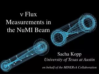
DSS system PC Beam emission shifted from Dα by ∆=0(Vbeam/c) cos Source parameters : Species mix (H+:H2+:H3+); Beam parameters : Perveance scans ( beam divergence ); Beam species distribution; Neutral beam fractions (H(E):H(E/2):H(E/3));Power fractions (P(E):P(E/2):P(E/3);
…and continues in the neutraliser… This particle has full energy, E These have half energy, E/2 These have one third energy, E/3 . There are three simple scenarios: H+ H2 H These three molecular ions have all been accelerated through the same potential, and therefore they all have the same energy. “E”. H2 H H H2+ The collisions with the neutraliser gas can cause the molecular ions to dissociate. H3+ H2 H H H
Channels for Beam Emission H*(E/2) H(E/3)
Ion species mix in the ion source (H+S:H2+S:H3+S) • Impurity content in the source • Ion species fractions : (H+ext:H2+ext:H3+ext ) • Beam species distribution: (Hik ,b ) • Neutral beam fractions: H(E):H(E/2):H(E/3) • Power fractions entering into Tokamak • Beam divergence
3d(15.6ns) 3p(5.4ns) 3s(158ns) 2p 2s DSS analysis : Corona model H-alpha transition diagram • i=H+,H2+,H3+(ext species) • k=0,1,-1(charge state) • Nl*(Ɛ): Excited neutral density at energy Ɛ=E,E/2 and E/3. • Nik : Beam species density at energies E,2E/3,E/2& E/3. • σik(Ɛʹ):Excitation cross section of a beam species. • Fik(Ɛʹ): Fraction of beam existing in a charge state k.
Species mix(source) Beam fractions and power fractions Species fractions(beam) Specie fractions C2 and C3 are intensity multiplication factors and they depend on beam energy and target thickness.
Results • Raw data for Dα peak • Doppler shifted full, half and third energy peaks • Impurity peak at E/18 • Shifted and impurity peaks fitted by analysis code using constrained MPI fit.
Results • Species fractions as a function of arc current. • Power fractions as a function of Extracted power.
Limitations of the Model • Assumption that radiation is instantaneous. • H*(3s) has longer life times (158 ns) • Major populating and depopulating processes are neglected. • Cascading from upper states • Collisional quenching of excited neutrals. • Need to apply modified corona model.
Obtaining the relative fractions… • These are calculated with a simple expression: • This shows the number of third energy particles relative to the number of full energy particles • F is flux of particles leaving the ion source, J is detected intensity • C is a constant, which looks like…
…this: • Thankfully, most of these terms can be ignored, because: • There will be no emission from ions (they have no electrons…) • We don’t care how many ions there are, because they get removed anyway… • So we have a much simpler expression to deal with • σ is the excitation cross-section and f is the fraction
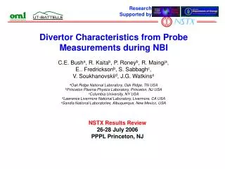
S K Allison, Reviews of Modern Physics,1958, 1137,4 Calculated Vs measured beam fractions ( 1X10¹⁶ molecules/cm2) Estimation of Beam fractions Beam fractions at 20KeV Formulation : K H Berkner, R V Pyle and J W Stearns, 1975, Nuclear fusion, 249-254,15. J Kim and H H Haselton, 1979, J.Appl.Phys,3802-3807,50. Cross sections : C F Barnett, Atomic data for nuclear fusion, 1990,Volume.1,Report ORNL-6086/V1, Oak ridge national laboratory.