Download
1 / 36
380 likes | 532 Views
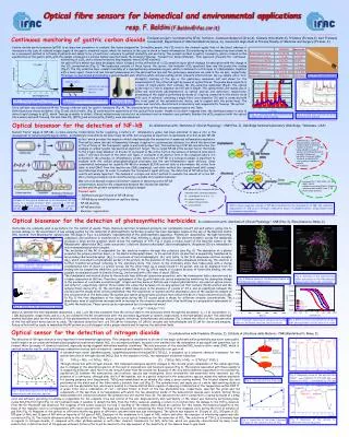
Optical fibre sensors for environmental monitoring at LHC and SLHC experiments.

E N D
Optical fibre sensors for environmental monitoring at LHC and SLHC experiments N. Beni(ATOMKI / CERN); G. Breglio (Federico II / Optosmart); S. Buontempo (INFN Napoli / CERN); M. Consales (Sannio); A. Cusano(Sannio / Optosmart); A. Cutolo(Sannio / Optosmart); M. Giordano (CNR Napoli / Optosmart); P. Petagna (CERN); Z. Skillasi(ATOMKI / CERN) • Fibre Optical Sensors (FOS) applications • Fibre Bragg Grating FOS (FBG) specificities • First FBG applications in HEP: T and e measurements in CMS • New R&D line: FBG as Relative Humidity sensors • Polyimide coated FBG as RH sensors: experimental results
Pout=k·RFilm·Pin • k is a constant • RFilm is the film reflectance Reflectivity -B [nm] ΔRfilm=f (ΔεFilm , ΔdFilm , Δεext) • εFilm is the complex dielectric constant of the film • dFilm is the film thickness • εext is the external medium dielectric constant • Concept of Fibre Optical Sensor (FOS) • Multipoint distributed sensor through fibre grating Single-mode optical fiber External medium • Single point sensor through fibre tip coating Sensitive layer
Main advantages of FOS technology • For a large number of environmental monitoring and industrial applications fiber-optic sensor technology now offers several advantages for significant metrological improvement through: • Immunity to electromagnetic interference • Lightweight • Possibility to work in hard environments • Intrinsic Radiation Hardness • High sensitivity, versatility and bandwidth • Simple multiplexing • Absence of electronic circuitry in the measurement area • This technology is suitable for remote measurements and it is, by definition, compatible with the fiber-optic communication networks
FOS fields of application Bandgap engineering Integrationwith: Photonicdevices Metal oxide particle layers Nanoporous Polymers Carbon nanotubes Microstructuration Tapering Tapered Fiber Micro-structured Fiber Gratings Long period Fiber Gratings Micro resonators Hollow core optical fiber Measuredparameters: Applicationto: Strain Temperature Vibration Refractiveindex Chemical detection Humidity Electric and Magneticfield 1 0.1 C° Up to 1 MHz 10-5 < 1 ppm < 1% Structuralhealthmonitoring Damage detection Aeronauticmonitoring Geodetical monitoring Enviromental monitoring Acoustic monitoring Railwaysmonitoring
Cladding Core Source LED Transmittedsignal Reflected signal Fibre Bragg Grating FOS l1,l2,…ln l2,…ln l1 L=l1/2neff • Where: • neffis the effective refractive index of the fibre • is the grating pitch • B is the reflected Bragg wavelength Any strain or temperature perturbationexperiencedby the FBG results in a Braggwavelengthshift
First use of FBG sensors in HEP: CMS In the last two years the CMS experiment at LHC accepted to pioneer the application of FOS (FBG) to an HEP experiment • ~ 100 T or e sensors placed in the following areas in CMS: • HF region negative side (Raiser and Castor table) • Tracker bulkhead on both sides (10-10 sensor) • Experimental Cavern (60) (in January 2011) (in 2009) Aim: • demonstrate feasibility • follow mechanical changes induced by magnetic field (HF-) • Monitor the T distribution in front of the Tracker • (2011) monitor the cavern environment
e measurement during 2011 magnet ramp-up Far side Near side
T distribution in front of the Tracker Z- Z+ One year record of temperature measured by FBG follows the activity of Tracker and provide information on the thermal mapping of the critical area between the TK and the EE
Additional FBG to map T in the cavern • Additional60 FBG T sensors has been installed inthe experimental cavern in January 2011 : • 23 sensors on wall near side • 3 sensors on ceiling +Z side • 23 sensors on wall far side • 8 sensors on shaft far side • 3 sensors on ceiling -Z side • Some HOURS of work to install all of them! • In the figures a snapshot of the T distribution on the rack balconies is shown 19.1 19.5 20.0 20.1 19.8 19.5 19.6 19.8 19.2 18.9 19.9 20.3 21.7 19.9 19.1 19.8 20.3 21.8 19.9 19.2 19.2 19.6 20.0 19.8 19.3 19.8 20.0 19.9 19.2 --- 18.7 --- 19.2 19.2 18.7 19.2 19.2 --- 19.2 19.3 19.6 19.6 19.5 Z- Z+ 19.5 19.7 19.4 Z+ Z-
A curiosity about T distribution in the shaft surface 16.4 Shaft FBGs are installed 16.4 16.6 16.9 16.8 17.1 17.5 Daily temperature peak of the top sensor appearing when shaft plug is open (every day a bit later than the previous one): effect of direct sunlight discriminated Shaft plug closed 18.6 cavern
Humidity sensing issues in HEP Trackers CURRENTLY AT CERN (typical) • HUMIDITY SENSOR SPECIFICATIONS FOR HEP TRACKING DETECTORS • Low mass • Small dimensions • Insensitivity to magnetic field • Operation at temperature down to -40 ˚C • Response to the full range [0, 100]% RH • Reduced number of wires needed • Radiation resistance to doses up to 1 MGy • HIH 4000 series by Honeywell • Small • Inexpencive • 3 wires for each measuring point • Accuracy of 3,5%RH • Response time 15s • Minimum operation temperature -40°C • Notradiationresistant!!!
Motivations for R&D on new RH sensors • Almost all miniaturized humidity sensors presently available on the market are electronic sensors (mainly capacitive-based, followed by resistive-based). • Despite all efforts, these sensors still fail to provide a complete set of favourable characteristics, e.g., good linearity, high sensitivity, low uncertainty, low hysteresis and rapid response time. • For an application in HEP detectors, one should add to this the sensitivity to electro-magnetic noise pick-up, the suitability for multi-point distributed measurements and the resistance to ionizing radiations. Nowadays – although important requirements on environmental control exist, in particular for Trackers – there is no miniaturized humidity sensor on the market well suited for HEP detector applications
Realizationofhumiditysensorbycoating the gratingswith a suitedpolymer. Sensingprinciple Absorbtionofmoistureby the polymericcoating Bragg wavelength shift Expansion of the coating (“swelling”) Strain induced on the FBG FBG2 RH SENSOR FBG1 T- SENSOR Temperature compensation is needed POLYIMIDE COATING FBG as relative humidity sensor • Bare FBG isinsensitivetohumidity. • Useof sensitive material ascoatingof the FBG to induce a mechanicaleffect. • Hygroscopicpolymersswelluponadsorptionof water molecules.
Starting point: polyimide coating 2002 2005 • Relative humidity range limited to 10 – 90 % RH • Temperature range limited to 10 ÷ 65 °C • Completely unexplored effect of ionizing radiations
RH testing / calibration facility @ CERN Test section Insulated confinement Ranges: 0% ≤ RH ≤ 100% -20 °C ≤ T ≤ +30 °C Chilled mirror Thermally controlled liner External air circulation (dry + saturated air mixer) Closed loop circulation (salt solution in box) Salt solution container (if needed)
Custom fabricated polyimide coated FBG • Naked FBG outsourced under strict specifications • In-house multiple dip coating + oven curing cycles with PI2525 HD MicrosystemPyralin Family 1 (thin): coating thickness = 8 mm Family 2 (thick): coating thickness = 17 mm
Low temperature & humidity properties Family 2 (thick): coating thickness = 17 mm (typical) Family 1 (thin): coating thickness = 8 mm (typical) NOTE: Time response very (too?) slow at T < 0 C Temperature sensitivity: Temperature sensitivity: ST=9.54 pm/°C±0.9% ST=10.08 pm/°C±12.4% Humidity sensitivity: Humidity sensitivity: SRH=0.42 pm/%RH±7,.% SRH=2.09 pm/%RH±19.6%
First ionizing irradiation dose: 10 kGy Perfect l peak invariance after first irradiation Family 1 (thin): coating thickness = 8 mm Family 2 (thick): coating thickness = 17 mm Note: Honeywell HIH 4000 dies (no signal) after 10 kGy ionizing irradiation dose
Further irradiation level: 50 kGy T = 0 C: before and after irradiation T = 20 C: before and after irradiation g-irradiation tests up to 50 kGy* show good radiation resistance and suggest no further variation after the first level (possibility of applying a “pre-stress”) * latest data at 100 kGy confirm the observation
More technical details and results? “Relative Humidity Monitoring by Polyimide-Coated Fiber Bragg Grating Sensors for High-Energy Physics Applications” Accepted to IEEE Sensors 2011 (Limerick-Ireland)
Further developments • Continue irradiation studies up to 1 MGy • Perform tests at intermediate T (accurate T dependence estimate) • Accurate measurement of response time in function of T • Develop reliable packaging for field operation • Study different kind of polymeric coatings (epoxies?) • Feasibility of different gratings for direct humidity reading (LPG) • Create a real network among all FOS developments suited for HEP (Full scale cryogenic thermometers, Magnetic field measurement, Dosimeters, CFRP and Silicon –embedded strain measurement,…) • Resubmission of the FOS4HEP MC ITN proposal ONGOING 2012 FUTURE
THANK YOU FOR YOUR ATTENTION! (RESERVE SLIDES FOLLOW)