Trilateral Euregio Cluster
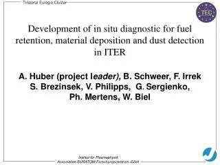
T. E. C. Trilateral Euregio Cluster. Development of in situ diagnostic for fuel retention, material deposition and dust detection in ITER. A. Huber (project l eader), B. Schweer, F. Irrek S. Brezinsek, V. Philipps, G . Sergienko, Ph. Mertens, W. Biel. Institut für Plasmaphysik

Trilateral Euregio Cluster
E N D
Presentation Transcript
T E C Trilateral Euregio Cluster Development of in situ diagnostic for fuel retention, material deposition and dust detection in ITER A. Huber (project leader), B. Schweer, F. Irrek S. Brezinsek, V. Philipps, G.Sergienko, Ph. Mertens, W. Biel Institut für Plasmaphysik Assoziation EURATOM-Forschungszentrum Jülich
T E C Trilateral Euregio Cluster • Urgent need to develop in situ diagnostic for fuel retention, material deposition and dust production generation, recognised by ITER (design change request Nr: ) • Proper gas balance should be a main method to measure fuel retention in a global way • No further information from post mortem tile analysis • Development of in situ laser based methods for fuel retention, material deposition and dust production to • support gas balance and enable (some) space resolution • determine amount and composition of material deposition (correlation with gas balance) • allow dust detection near deposition dominated areas Institut für Plasmaphysik Assoziation EURATOM-Forschungszentrum Jülich
T E C Methods During discharges Smooth (≈ 1 ms) laser desorption with spectroscopy to measure fuel retention Laser ablation with spectroscopyto measure material deposition Rayleigh / Mie scattering for dust monitoring In-between discharges Laser-induced breakdown spectroscopy (LIBS) for material deposition and composition Idea: develop a single laser and mirror based system for all 4 methods which can scan some part of inner wall/divertor area in ITER
T E C Laser-induced desorption (LID): Laser without Q-switch at 1064 or 532 nm; Pulse duration: up to 3 ms; Total energy: up to 120 J. Rayleigh/Mie scattering: Laser without Q-switch at 1064 or 532 nm Pulse duration: up to 10 ms Total energy: up to 120 J. Operating modes Laser-induced Ablation (LIA): Laser with Q-switch at 532 nm; Pulse duration: up to 10 ns; Total energy: 5 J. Laser-induced Breakdown Spectroscopy (LIBS): Laser with Q-switch at 532 nm Pulse duration: up to 10 ns; Total energy: 5 J. Operation without plasma Strategy: a Nd:YAG laser operating with/without Q-switch
T E C YAG Laser Status of work : laser induced desorption Pulse duration: 0.1-20ms Spot size : 4-20 mm2 Power density: 20-120 kW/cm2 Optical diagnostic D (H/D ratio) D, Dγ, CD CII, CIII Fiber coupling Fast IR linear array camera Quadrupol MS Limiter lock system 1 Movable target holder TEXTOR Tokamak Laboratory Device
T E C Higher P, t Laser-Spot ( a-C:D on Graphite) Thermal desorption: qualification in Lab experiments 180 nm a-CH layer on graphite Mass 4 Closed valves Mean power Density: 95 kW/cm2 SIMS: 96% Reduction of D-Inventory,
T E C Application in TEXTOR with Ha Spectroscopy Graphite EK98 target exposed to TEXTOR plasma, LDS measured 45 nm (2.2x10¹⁷ H/cm2), ±30% Laser-desorption of pre-coated samples for calibration LID has been qualified in TEXTOR to measure in situ and shot by shot fuel retention in C materials ( PSI contribution)
Application in TEXTOR with Ha Spectroscopy Plasma LCFS 46 47 48 49 50 46 47 48 49 50 46 47 48 49 50 Radial Position r / cm Radial Position r / cm Radial Position r / cm FWHM: 3.3 cm FWHM: 2.0 cm FWHM: 5.3 cm Quantification of H light needs large optical view Good agreement with S/XB literature values for r < 49 at TEXTOR 5060 5130 5040
T E C with Q-switch P t=20ns Q=20J Amplifiers mirror Telescope He-Ne Laser Plasma Ablation: qualification in TEXTOR Experimental setup: limiter lock III
T E C 600 r = 50 cm Sspot= 0.16 cm2 First laser shot 500 Second laser shot 400 CII(658nm) a H (656nm) intensity / a.u. CII(589nm) 300 CII(678.4nm) 200 100 0 580 600 620 640 660 680 wavelength / nm Trilateral Euregio Cluster Ablation: qualification in TEXTOR Tungsten substrate Tungsten test limiter with 140 nm a-C:D coating Ruby Laser (20 J max) in 20 ns time scale r = 48 cm Sspot= 0.3 cm2 r = 48 cm Sspot= 0.4 cm2 Institut für Plasmaphysik Assoziation EURATOM-Forschungszentrum Jülich
T E C TEXTOR test limiter (Ti), coated by Textor plasma larger laser spot reduced spot, same power Ti melting For C-layers deposited on W and Ti, an operational window exits for complete C layer ablation (one laser shot) without ablation of substrate
T E C Summary Laser fuel desorption and material ablation with spectroscopic detection in TEXTOR standard plasmas has been sufficiently qualified in TEXTOR Next steps: Conceptual design of a system for possible ITER application (2008) Procurement of a laser with ≈ 120 J for ≈ 10 ms. Manufacture of beam line and detection (2009) Testing of the system in the laboratory (2010) Installation and testing of the system in a fusion plasma 2011 (e.g. TEXTOR)