Download
1 / 30
370 likes | 640 Views
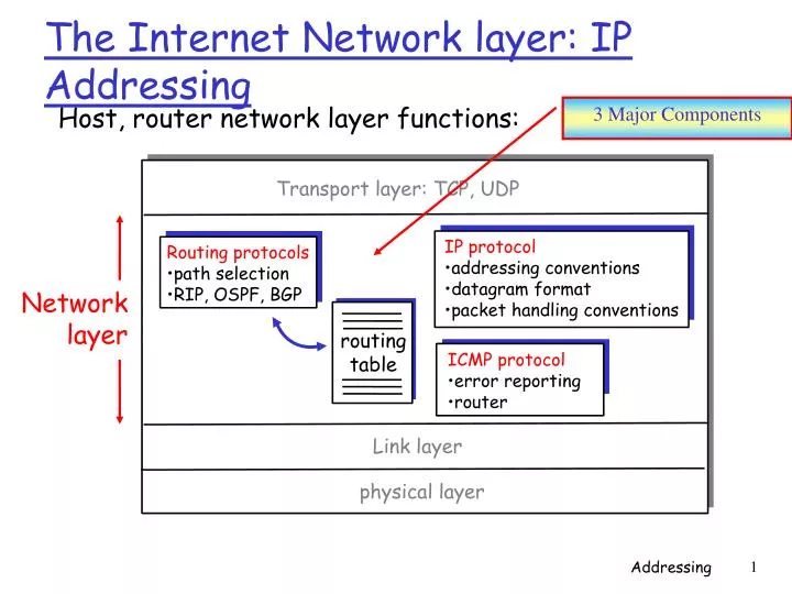
Transport layer: TCP, UDP. IP protocol addressing conventions datagram format packet handling conventions. Routing protocols path selection RIP, OSPF, BGP. Network layer. routing table. Link layer. physical layer. The Internet Network layer: IP Addressing. 3 Major Components.

E N D
Transport layer: TCP, UDP IP protocol • addressing conventions • datagram format • packet handling conventions Routing protocols • path selection • RIP, OSPF, BGP Network layer routing table Link layer physical layer The Internet Network layer: IP Addressing 3 Major Components Host, router network layer functions: ICMP protocol • error reporting • router
223.1.1.1 223.1.2.1 223.1.1.2 223.1.2.9 223.1.1.4 223.1.2.2 223.1.3.27 223.1.1.3 223.1.3.2 223.1.3.1 223.1.1.1 = 11011111 00000001 00000001 00000001 223 1 1 1 IP Addressing: introduction Dotted-decimal notation • IP address: 32-bit identifier for host, router interface • interface: connection between host, router and physical link • Routers typically have multiple interfaces • host may have multiple interfaces • IP addresses associated with interface, not host, router Must be globally unique
IP Address See Excel Sheet
223.1.1.1 223.1.2.1 223.1.1.2 223.1.2.9 223.1.1.4 223.1.2.2 223.1.3.27 223.1.1.3 LAN 223.1.3.2 223.1.3.1 network consisting of 3 IP networks (for IP addresses starting with 223, first 24 bits are network address) /24 – Network mask; leftmost 24 bits identify the network address IP Addressing One IP Network: 223.1.1.0/24 • IP address: • network part (high order bits) • host part (low order bits) • What is a network ? (from IP address perspective) • device interfaces with same network part of IP address • can physically reach each other without intervening router
223.1.1.2 223.1.1.1 223.1.1.4 223.1.1.3 223.1.7.0 223.1.9.2 223.1.9.1 223.1.7.1 223.1.8.1 223.1.8.0 223.1.2.6 223.1.3.27 Interconnected system consisting of six networks 223.1.2.1 223.1.2.2 223.1.3.1 223.1.3.2 IP Addressing How to find the networks? • Detach each interface from router, host • create islands of isolated networks
class 1.0.0.0 to 127.255.255.255 A network 0 host 128.0.0.0 to 191.255.255.255 B network 10 host 192.0.0.0 to 223.255.255.255 C network host 110 224.0.0.0 to 239.255.255.255 D multicast address 1110 32 bits IP Addressing given notion of network, let's re-examine IP addresses: Note: Reserving 216= 65K for host addresses would be wasteful for a 2K hosts requirement Classful addressing:
host part network part 11001000 0001011100010000 00000000 200.23.16.0/23 IP Addressing: CIDR (1993) IETF standardized on CIDR • Classful addressing: • inefficient use of address space, address space exhaustion • e.g., class B net allocated enough addresses for 65K hosts, even if only 2K hosts in that network • CIDR:Classless Inter Domain Routing • network portion of address of arbitrary length • address format: a.b.c.d/x, where x is # bits in network portion of address
host part network part 11001000 0001011100010000 00000000 200.23.16.0/23 IP addressing: Masks • Masks are commonly used in some configuration files • Simply convert the mask to binary and check which is the network part and which is the host part • e.g., for a 23 bits network and 9 bits host, the mask would be • 255.255.254.0 • Or 1111 1111 1111 1111 1111 1110 0000 0000 • Possible values for masks are combinations where there are only 1's at the left side and 0's on the right side of the mask
IP addresses: how to get one? Network (network portion): • get allocated portion of ISP's address space for use within an organisation’s subnet: ISP's block 11001000 00010111 00010000 00000000 200.23.16.0/20 Organization 0 11001000 00010111 00010000 00000000 200.23.16.0/23 Organization 1 11001000 00010111 00010010 00000000 200.23.18.0/23 Organization 2 11001000 00010111 00010100 00000000 200.23.20.0/23 ... ….. …. …. Organization 7 11001000 00010111 00011110 00000000 200.23.30.0/23
Hierarchical addressing allows efficient advertisement of routing information: Organization 0 200.23.16.0/23 Organization 1 Send me anything with addresses beginning 200.23.16.0/20 200.23.18.0/23 Organization 2 . 200.23.20.0/23 Fly-By-Night-ISP . . . Internet . . Organization 7 200.23.30.0/23 Send me anything with addresses beginning 199.31.0.0/16 ISPs-R-Us Hierarchical addressing: route aggregation Ability to use single network prefix to advertise multiple networks
ISPs-R-Us has a more specific route to Organization 1 Organization 0 200.23.16.0/23 Send me anything with addresses beginning 200.23.16.0/20 Organization 2 . 200.23.20.0/23 Fly-By-Night-ISP . . . Internet . . Organization 7 200.23.30.0/23 Send me anything with addresses beginning 199.31.0.0/16 or 200.23.18.0/23 ISPs-R-Us Organization 1 200.23.18.0/23 Hierarchical addressing: more specific routes Uses longest prefix matching rule – longest most specific address matching the destination address
IP addressing: the last word... Q: How does an ISP get block of addresses? A: ICANN: Internet Corporation for Assigned Names and Numbers • allocates addresses • manages DNS • assigns domain names, resolves disputes Global authority Based on guidelines in RFC 2050
IP addresses: how to get one? Obtaining Host Addresses: • hard-coded by system admin (in a file) • DHCP:Dynamic Host Configuration Protocol: dynamically get address: plug-and-play • host broadcasts DHCP discovermsg • DHCP server responds with DHCP offermsg • host requests IP address: DHCP requestmsg • DHCP server sends address: DHCP ackmsg
DHCP discover src : 0.0.0.0, 68 dest.: 255.255.255.255,67 yiaddr: 0.0.0.0 transaction ID: 654 Within a UDP packet, to port 67 DHCP client-server scenario arriving client DHCP server: 223.1.2.5 DHCP offer src: 223.1.2.5, 67 dest: 255.255.255.255, 68 yiaddrr: 223.1.2.4 transaction ID: 654 Lifetime: 3600 secs DHCP request src: 0.0.0.0, 68 dest:: 255.255.255.255, 67 yiaddrr: 223.1.2.4 transaction ID: 655 Lifetime: 3600 secs time DHCP ACK src: 223.1.2.5, 67 dest: 255.255.255.255, 68 yiaddrr: 223.1.2.4 transaction ID: 655 Lifetime: 3600 secs Network Layer
Network Address Translation (NAT) An approach to address allocation (RFC 2663, 3022) Multiplying the number of devices sharing the same IP Address 10.0.0.1 S=138.76.29.7, 5001 D=128.119.40.186, 80 S=10.0.0.1, 3345 D=128.119.40.186, 80 10.0.0.2 S=128.119.40.186, 80 D=138.76.29.7, 5001 S=128.119.40.186, 80 D=10.0.0.1, 3345 10.0.0.3 Router’s IP Address – taken from ISP’s DHCP server Address for devices – from DHCP server run by the router NAT-enabled router hides details of the home network from the outside world; behaves like a single device with a single IP address (does not appear as a router anymore)
Network Address Translation (NAT) An approach to address allocation (RFC 2663, 3022) 10.0.0.1 S=10.0.0.1, 3345 D=128.119.40.186, 80 10.0.0.2 10.0.0.3 NAT router generates a new source port source number for each datagram it receives from the private network (realm of private addresses) Address space 10.0.0.0/8 is one of three portions of the IP address space that is reserved in RFC1918 for a private network
Network Address Translation (NAT) An approach to address allocation (RFC 2663, 3022) 10.0.0.1 S=10.0.0.1, 3345 D=128.119.40.186, 80 10.0.0.2 10.0.0.3 PROBLEMS with NAT: • Violates the use of port numbers • Routers are supposed to process packets only up to layer 3 • Violates End-to-End argument; Host addresses should not be modified • Interferes with P2P applications. A host behind a NAT-enabled router cannot act as a server. • Suggestion by purists in the IETF: IPv6 should be used instead!
routing table in A Dest. Net. next router Nhops 223.1.1 1 223.1.2 223.1.1.4 2 223.1.3 223.1.1.4 2 source IP addr misc fields dest IP addr data A 223.1.1.1 • datagram remains unchanged, as it travels from source to destination • Addresses are the fields of interest here 223.1.2.1 223.1.1.2 223.1.2.9 223.1.1.4 B 223.1.2.2 E 223.1.3.27 223.1.1.3 223.1.3.2 223.1.3.1 Example #1 Getting a datagram from source to dest. IP datagram: Host A learns that Host B can be reached directly via its outgoing interface. In turn, the Link-Layer protocol delivers the datagram to Host B. (details on next slide)
Dest. Net. next router Nhops misc fields data 223.1.1.1 223.1.1.3 223.1.1 1 223.1.2 223.1.1.4 2 Starting at A, given IP datagram addressed to B: • look up net. address of B • finds B is on same net. as A • link layer will send datagram directly to B inside link-layer frame • B and A are directly connected 223.1.3 223.1.1.4 2 A 223.1.1.1 223.1.2.1 223.1.1.2 223.1.2.9 223.1.1.4 B 223.1.2.2 E 223.1.3.27 223.1.1.3 223.1.3.2 223.1.3.1 Example #1 Getting a datagram from source to dest. B is on the same network as A
Dest. Net. next router Nhops misc fields data 223.1.1.1 223.1.2.2 223.1.1 1 223.1.2 223.1.1.4 2 Starting at A, dest. E: • look up network address of E • E on different network • A, E not directly attached • routing table: next hop router to E is 223.1.1.4 • link layer sends datagram to router 223.1.1.4 inside link-layer frame • datagram arrives at 223.1.1.4 • continued….. 223.1.3 223.1.1.4 2 A 223.1.1.1 223.1.2.1 223.1.1.2 223.1.2.9 223.1.1.4 B 223.1.2.2 E 223.1.3.27 223.1.1.3 223.1.3.2 223.1.3.1 Example #2 Getting a datagram from source to dest. Continued on next slide…
Dest. next misc fields network router Nhops interface data 223.1.1.1 223.1.2.2 223.1.1 - 1 223.1.1.4 223.1.2 - 1 223.1.2.9 Arriving at 223.1.1.4, destined for 223.1.2.2 • look up network address of E • E on same network as router’s interface 223.1.2.9 • Router & E are directly attached to each other • link layer sends datagram to 223.1.2.2 inside link-layer frame via interface 223.1.2.9 • datagram arrives at 223.1.2.2!!! 223.1.3 - 1 223.1.3.27 A 223.1.1.1 223.1.2.1 223.1.1.2 223.1.2.9 223.1.1.4 B 223.1.2.2 E 223.1.3.27 223.1.1.3 223.1.3.2 223.1.3.1 Example #2 Getting a datagram from source to dest.
Exercise#1 Show the forwarding process if a packet arrives at R1 in the figure with the destination address 180.70.65.140. subnet: 180.70.65.128/25 180.70.65.135/25 m0 subnet: 201.4.16.0/22 subnet: 201.4.22.0/24 m1 m3 201.4.22.3/24 201.4.16.2/22 R2 R1 m2 180.70.65.194/26 subnet: 180.70.65.192/26 rest of the Internet 180.70.65.200/26
Exercise#1 Routing Table for Router 1 (R1) (continuation...) Show the forwarding process if a packet arrives at R1 in the figure with the destination address 180.70.65.140. See the Excel worksheet to find the solution.
Exercise#2 Show the forwarding process if a packet arrives at R1 in the figure with the destination address 18.24.32.78. subnet: 180.70.65.128/25 180.70.65.135/25 m0 subnet: 201.4.16.0/22 subnet: 201.4.22.0/24 m1 m3 201.4.22.3/24 201.4.16.2/22 R1 R2 m2 180.70.65.194/26 subnet: 180.70.65.192/26 rest of the Internet 180.70.65.200/26
Exercise#2 Show the forwarding process if a packet arrives at R1 in the figure with the destination address 18.24.32.78. SOLUTION: All masks are applied, one by one, to the destination address, but no matching network address is found. When it reaches the end of the table, the module gives the next-hop router’s address 180.70.65.200 and interface number m2 to ARP (link-layer protocol). This is probably an out-going packet that needs to be sent, via the default router, to someplace else in the internet.
IP datagram format Some header fields are optional. This helps to indicate where data actually begins IP protocol version number 32 bits total datagram (header + data) length (bytes) header length (bytes) type of service header len ver length for fragmentation/ reassembly fragment offset “type” of data flgs 16-bit identifier max number remaining hops (decremented at each router) upper layer time to live Internet checksum Calculated based on the header only (treated as sequence of 16bits) 32 bit source IP address 32 bit destination IP address upper layer protocol to deliver payload to E.g. timestamp, record route taken, specify list of routers to visit. Options (if any) data (variable length, typically a TCP or UDP segment) e.g. IP Broadcast address: 255.255.255.255 – message is delivered to all hosts on the same network
IP Fragmentation &Reassembly Performed by DESTINATION HOST • network links have MTU (max. transmission unit) - largest possible link-level frame. • different link types, different MTUs • large IP datagram divided (“fragmented”) within net • one datagram becomes several datagrams (FRAGMENTS) • “reassembled” only at final destination • IP header bits used to identify, order related fragments fragmentation: in: one large datagram out: 3 smaller datagrams reassembly Supported by IP: MTUs of at least 576 bytes MSS=536 bytes, TCP segment header=20 bytes, IP datagram header = 20 bytes
IP Fragmentation and Reassembly length =4000 ID =x fragflag =0 offset =0 Multiple of 8 bytes One large datagram becomes several smaller datagrams payload length =1500 ID =x flag =1 Offset 0 1,480 bytes [0,1479] length =1500 ID =x flag =1 Offset 185 (i.e. 185 * 8 =1480) 1,480 bytes [1480,2959] length =1040 ID =x flag =0 Offset 370 (i.e. 370*8=2960) 1,020 bytes [2960, 3979] Total Size of Datagram = 4,000 bytes 20 bytes of IP header, 3,980 bytes of IP Payload
ICMP: Internet Control Message Protocol • used by hosts, routers, gateways to communicate network-level information • error reporting: unreachable host, network, port, protocol • echo request/reply (used by ping) • Part of IP, but architecturally lies “above” IP: • ICMP msgsare carried as IP payload • ICMP message: comprised of type, code plus first 8 bytes of IP datagram causing error TypeCodedescription 0 0 echo reply (ping) 3 0 dest. network unreachable 3 1 dest host unreachable 3 2 dest protocol unreachable 3 3 dest port unreachable 3 6 dest network unknown 3 7 dest host unknown 4 0 source quench (congestion control - not used) 8 0 echo request (ping) 9 0 route advertisement 10 0 router discovery 11 0 TTL expired 12 0 bad IP header