Download
1 / 52
550 likes | 821 Views
Explore the internal details and creation of reservoir for Koyna Dam's hydroelectric project, examining the specific speed, geometry, and performance analysis of the turbine system.

E N D
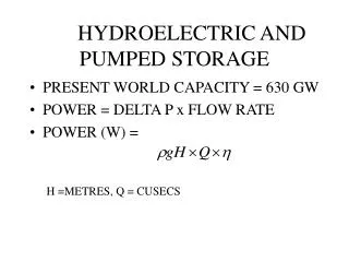
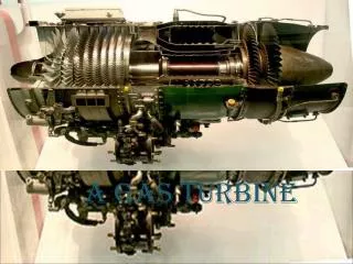
Design & Analysis of Pelton Wheel Turbine P M V Subbarao Professor Mechanical Engineering Department Internal Details of the Machine….
Koyna Hydro Electric Project Koyna Dam from the catchment area of about 891.78 Sq. Km • Koyna river rises in the Mahabaleshwar, a famous hill station in the hill range of Sahyadri. • It flows in a north - south direction almost parallel to the Arabian Sea coast for a distance of 65 Kms.
Details of Koyna Hydro Electric Project • Number of units: 4 • Capacity of each unit=250MW • Head • Normal Head=415m • Maximum Head=510m
Selection of Speed of A Turbo Machine Zp : Number of pairs of poles of the generator
Questions to be Answered • Is it possible to change number of units in Stage IV? • What is the allowable speed of the generator for each unit, if number of units is 2, 5, 6 or 7?
Design of Any Selected Pelton Wheel Unit • Different capacities for each sub-group. • Design for Normal Head. • Assume an overall efficiency: 90 – 94% • Calculate the required flow rate.
THE CONDUIT SYSTEM • Water from the storage is diverted into the main conduit system through a 3,370ft long intake channel and an intake tower, trash racks and two intake gates each 21ftX8ft. • The head race tunnel is 12,000ft long and 21ft in diameter. • It is concrete lined for the whole of the length expect for the last 1600ft at the surge end where 17ft diameter steel lining is provided. • The diameter of the tunnel, in the stretch of steel lining is reduced on ground of economy
Open Channel Gravity Flow Channel Bed Slope
Design of Penstock In general But maximum allowable value is 10 m/s Maximum allowable head loss in Penstock =2 to 4% of available head
Design of Distributor Penstock Q
The Nozzle and Jet : A Key Step in Design b a d0 djet,VC Free Surface Shape for Maximum Power
Initial guess for Diameter of the Jet at the outlet, do It is important to find out the VC and outlet jet diameters/areas
Geometrical Relations for Nozzle 1.1dO – 1.3dO 2dO – 2.4dO dO 0.8dO – 0.9dO 1.2dO – 1.4dO 5dO – 9dO
Performance Analysis of Nozzle-Spear Valve Ideal Nozzle-spear Valve: Along flow direction Real Nozzle-spear Valve:
Efficiency of Spear Nozzle Valve Acceptable Range: 97.5% -- 99%
Geometrical Relations for Nozzle The values of α varies between 20 to 30° whereas β varies from 30 to 45°.
Industrial Correlations for Jet Area variation with stroke Optimal value of Outlet jet area, ao s is the displacement of spear
Mean Diameter of Pelton Runner Mean diameter or Pitch circle diameter: Dwheel Circumferential velocity of the wheel, Uwheel
Experimental values of Wheel diameter to jet diameter Higher ratios are preferred for better efficiency. Modern wheels for high heads use ratios as high as 30!
III II IV V I Empirical Geometry of Bucket Shape C 2bi DW S A be B
Empirical Relations for Bucket Geometry • A = 2.8 djet,VC to 3.2 djet,VC • B = 2.3 djet,VC to 2.8 djet,VC • C= 0.6 djet,VC to 0.9 djet,VC • bi = 50 to 80 • be is varied from section I to section V • I: 300 to 460 • II: 200 to 300 • III: 100 to 200 • IV: 50 to 160 • V: 00 to 50
d RW w RP q y dO, Vj,O lj Number of Buckets
Maximum allowable angle between two successive buckets Minimum number of buckets Dr Taygun has suggested an empirical relation for z
Empirical Relations for Bucket Cutout • S = 0,95djet,VC to 1.05 djet,VC • d1= 0.18 djet,VC to 0.2 djet,VC • d2 = 0,95djet,VC to 1.05 djet,VC
Vjet Ublade be Ublade Vrel,jet,exit Absolute and Relative Paths of Jet : Orthogonal Interactions ae Vjet,exit