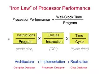

Processor Organization and Performance
E N D
Presentation Transcript
Processor Organization and Performance Chapter 6 S. Dandamudi
Introduction Number of addresses 3-address machines 2-address machines 1-address machines 0-address machines Load/store architecture Flow control Branching Procedure calls Delayed versions Parameter passing Instruction set design issues Operand types Addressing modes Instruction types Instruction formats Microprogrammed control Implementation issues Performance Performance metrics Execution time calculation Means of performance The SPEC benchmarks Outline S. Dandamudi
Introduction • We discuss three processor-related issues • Instruction set design issues • Number of addresses • Addressing modes • Instruction types • Instruction formats • Microprogrammed control • Hardware implementation • Software implementation • Performance issues • Performance metrics • Standards S. Dandamudi
Number of Addresses • Four categories • 3-address machines • 2 for the source operands and one for the result • 2-address machines • One address doubles as source and result • 1-address machine • Accumulator machines • Accumulator is used for one source and result • 0-address machines • Stack machines • Operands are taken from the stack • Result goes onto the stack S. Dandamudi
Number of Addresses (cont’d) • Three-address machines • Two for the source operands, one for the result • RISC processors use three addresses • Sample instructions add dest,src1,src2 ; M(dest)=[src1]+[src2] sub dest,src1,src2 ; M(dest)=[src1]-[src2] mult dest,src1,src2 ; M(dest)=[src1]*[src2] S. Dandamudi
Number of Addresses (cont’d) • Example • C statement A = B + C * D – E + F + A • Equivalent code: mult T,C,D ;T = C*D add T,T,B ;T = B+C*D sub T,T,E ;T = B+C*D-E add T,T,F ;T = B+C*D-E+F add A,T,A ;A = B+C*D-E+F+A S. Dandamudi
Number of Addresses (cont’d) • Two-address machines • One address doubles (for source operand & result) • Last example makes a case for it • Address T is used twice • Sample instructions load dest,src; M(dest)=[src] add dest,src; M(dest)=[dest]+[src] sub dest,src; M(dest)=[dest]-[src] mult dest,src; M(dest)=[dest]*[src] S. Dandamudi
Number of Addresses (cont’d) • Example • C statement A = B + C * D – E + F + A • Equivalent code: load T,C ;T = C mult T,D ;T = C*D add T,B ;T = B+C*D sub T,E ;T = B+C*D-E add T,F ;T = B+C*D-E+F add A,T ;A = B+C*D-E+F+A S. Dandamudi
Number of Addresses (cont’d) • One-address machines • Uses special set of registers called accumulators • Specify one source operand & receive the result • Called accumulator machines • Sample instructions load addr; accum = [addr] store addr; M[addr] = accum add addr; accum = accum + [addr] sub addr; accum = accum - [addr] mult addr; accum = accum * [addr] S. Dandamudi
Number of Addresses (cont’d) • Example • C statement A = B + C * D – E + F + A • Equivalent code: load C ;load C into accum mult D ;accum = C*D add B ;accum = C*D+B sub E ;accum = B+C*D-E add F ;accum = B+C*D-E+F add A ;accum = B+C*D-E+F+A store A ;store accum contents in A S. Dandamudi
Number of Addresses (cont’d) • Zero-address machines • Stack supplies operands and receives the result • Special instructions to load and store use an address • Called stack machines (Ex: HP3000, Burroughs B5500) • Sample instructions push addr; push([addr]) pop addr; pop([addr]) add ; push(pop + pop) sub ; push(pop - pop) mult ; push(pop * pop) S. Dandamudi
Number of Addresses (cont’d) • Example • C statement A = B + C * D – E + F + A • Equivalent code: push E sub push C push F push D add Mult push A push B add add pop A S. Dandamudi
Number of Addresses (cont’d) S. Dandamudi
Load/Store Architecture • Instructions expect operands in internal processor registers • Special LOAD and STORE instructions move data between registers and memory • RISC and vector processors use this architecture • Reduces instruction length S. Dandamudi
Load/Store Architecture (cont’d) • Sample instructions load Rd,addr;Rd = [addr] store addr,Rs;(addr) = Rs add Rd,Rs1,Rs2;Rd = Rs1 + Rs2 sub Rd,Rs1,Rs2;Rd = Rs1 - Rs2 mult Rd,Rs1,Rs2;Rd = Rs1 * Rs2 S. Dandamudi
Number of Addresses (cont’d) • Example • C statement A = B + C * D – E + F + A • Equivalent code: load R1,B mult R2,R2,R3 load R2,C add R2,R2,R1 load R3,D sub R2,R2,R4 load R4,E add R2,R2,R5 load R5,F add R2,R2,R6 load R6,A store A,R2 S. Dandamudi
Flow of Control • Default is sequential flow • Several instructions alter this default execution • Branches • Unconditional • Conditional • Delayed branches • Procedure calls • Delayed procedure calls S. Dandamudi
Flow of Control (cont’d) • Branches • Unconditional • Absolute address • PC-relative • Target address is specified relative to PC contents • Example: MIPS • Absolute address j target • PC-relative b target S. Dandamudi
Flow of Control (cont’d) S. Dandamudi
Flow of Control (cont’d) • Branches • Conditional • Jump is taken only if the condition is met • Two types • Set-Then-Jump • Condition testing is separated from branching • Condition code registers are used to convey the condition test result • Example: Pentium code cmp AX,BX je target S. Dandamudi
Flow of Control (cont’d) • Test-and-Jump • Single instruction performs condition testing and branching • Example: MIPS instruction beq Rsrc1,Rsrc2,target • Jumps to target if Rsrc1 = Rsrc2 • Delayed branching • Control is transferred after executing the instruction that follows the branch instruction • This instruction slot is called delay slot • Improves efficiency S. Dandamudi
Flow of Control (cont’d) • Procedure calls • Requires two pieces of information to return • End of procedure • Pentium • uses ret instruction • MIPS • uses jr instruction • Return address • In a (special) register • MIPS allows any general-purpose register • On the stack • Pentium S. Dandamudi
Flow of Control (cont’d) S. Dandamudi
Flow of Control (cont’d) Delay slot S. Dandamudi
Parameter Passing • Two basic techniques • Register-based • Internal registers are used • Faster • Limit the number of parameters • Stack-based • Stack is used • More general • Recent processors use • Register window mechanism • Examples: SPARC and Itanium (discussed in later chapters) S. Dandamudi
Operand Types • Instructions support basic data types • Characters • Integers • Floating-point • Instruction overload • Same instruction for different data types • Example: Pentium mov AL,address ;loads an 8-bit value mov AX,address ;loads a 16-bit value mov EAX,address ;loads a 32-bit value S. Dandamudi
Operand Types • Separate instructions • Instructions specify the operand size • Example: MIPS lb Rdest,address ;loads a byte lh Rdest,address ;loads a halfword ;(16 bits) lw Rdest,address ;loads a word ;(32 bits) ld Rdest,address ;loads a doubleword ;(64 bits) S. Dandamudi
Addressing Modes • Refers to how the operands are specified • Operands can be in three places • Registers • Register addressing mode • Part of instruction • Constant • Immediate addressing mode • All processors support these two addressing modes • Memory • Difference between RISC and CISC • CISC supports a large variety of addressing modes • RISC follows load/store architecture S. Dandamudi
Addressing Modes (cont’d) • Most RISC processors support two memory addressing modes • address = Register + constant • address = Register + Register • CISC processors like Pentium support a variety of addressing modes • Motivation: To efficiently support high-level language data structures • Example: Accessing a 2-D array S. Dandamudi
Instruction Types • Several types of instructions • Data movement • Pentium: mov dest,src • Some do not provide direct data movement instructions • Indirect data movement add Rdest,Rsrc,0 ;Rdest = Rsrc+0 • Arithmetic and Logical • Arithmetic • Integer and floating-point, signed and unsigned • add, subtract, multiply, divide • Logical • and, or, not, xor S. Dandamudi
Instruction Types (cont’d) • Condition code bits • S: Sign bit (0 = +, 1= -) • Z: Zero bit (0 = nonzero, 1 = zero) • O: Overflow bit (0 = no overflow, 1 = overflow) • C: Carry bit (0 = no carry, 1 = carry) • Example: Pentium cmp count,25 je target S. Dandamudi
Instruction Types (cont’d) • Flow control and I/O instructions • Branch • Procedure call • Interrupts • I/O instructions • Memory-mapped I/O • Most processors support memory-mapped I/O • No separate instructions for I/O • Isolated I/O • Pentium supports isolated I/O • Separate I/O instructions in AX,io_port ;read from an I/O port out io_port,AX ;write to an I/O port S. Dandamudi
Instruction Formats • Two types • Fixed-length • Used by RISC processors • 32-bit RISC processors use 32-bits wide instructions • Examples: SPARC, MIPS, PowerPC • 64-bit Itanium uses 41-bit wide instructions • Variable-length • Used by CISC processors • Memory operands need more bits to specify • Opcode • Major and exact operation S. Dandamudi
Instruction Formats (cont’d) S. Dandamudi
Microprogrammed Control • Introduction in Chapter 1 • 1-bus datapath • Assume all entities are 32-bit wide • PC register • Program counter • IR register • Holds the instruction to be executed • MAR register • Address of the operand to be stored in memory • MDR register • Holds the operand for memory operations S. Dandamudi
Microprogrammed Control (cont’d) 1-bus datapath S. Dandamudi
Microprogrammed Control (cont’d) ALU circuit details S. Dandamudi
Microprogrammed Control (cont’d) • Has 32 32-bit general-purpose registers • Interface only with the A-bus • Each register has two control signals • Gxin and Gxout • Control signals used by the other registers • PC register: • PCin, PCout, and PCbout • IR register: • IRout and IRbin • MAR register: • MARin, MARout, and MARbout • MDR register: • MDRin, MDRout, MDRbin and MDRbout S. Dandamudi
Microprogrammed Control (cont’d) Memory interface implementation details S. Dandamudi
Microprogrammed Control (cont’d) add %G9,%G5,%G7 Implemented as • Transfer G5 contents to A register • Assert G5out and Ain • Place G7 contents on the A bus • Assert G7out • Instruct ALU to perform addition • Appropriate ALU function control signals • Latch the result in the C register • Assert Cin • Transfer contents of the C register to G9 • Assert Cout and G9in S. Dandamudi
Microprogrammed Control (cont’d) • Example instruction groups • Load/store • Moves data between registers and memory • Register • Arithmetic and logic instructions • Branch • Jump direct/indirect • Call • Procedures invocation mechanisms • More… S. Dandamudi
Microprogrammed Control (cont’d) High-level FSM for instruction execution S. Dandamudi
Microprogrammed Control (cont’d) • Implementation • Hardware • Typical approach in RISC processors • Software • Typical approach in CISC processors • Hardware implementation • PLA based implementation shown • Three control signals • Opcode via the IR register • Status and condition codes • Counter to keep track of the steps in instruction execution S. Dandamudi
Microprogrammed Control (cont’d) Controller implementation S. Dandamudi
Microprogrammed Control (cont’d) • Software implementation • Typically used in CISC • Hardware implementation is complex and expensive • Example add %G9,%G5,%G7 • Three steps S1 G5out: Ain; S2 G7out: ALU=add: Cin; S3 Cout: G9in: end; S. Dandamudi
Microprogrammed Control (cont’d) • Uses a microprogram to generate the control signals • Encode the signals of each step as a codeword • Called microinstruction • A instruction is expressed by a sequence of codewords • Called microroutine • Microprogram essentially implements the FSM discussed before • A simple microprogram structure is on the next slide S. Dandamudi
Microprogrammed Control (cont’d) Simple microcode organization S. Dandamudi
Microprogrammed Control (cont’d) • A simple microcontroller can execute a microprogram to generate the control signals • Control store • Stores microprogram • Uses mPC • Similar to PC • Address generator • Generates appropriate address depending on the • Opcode, and • Condition code inputs S. Dandamudi
Microprogrammed Control (cont’d) Microcontroller S. Dandamudi
Microprogrammed Control (cont’d) • Problems with previous design: • Makes microprograms long by replicating the common parts of microcode • Efficient way: • Keep only one copy of common code • Use branching to jump to the appropriate microroutine S. Dandamudi