Download
1 / 18
180 likes | 205 Views
Explore the innovative design and functionality of the FEC in the EM calorimeter, discussing radiation hard technology, system testing, and component specifications for efficient particle detection.

E N D
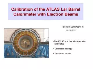
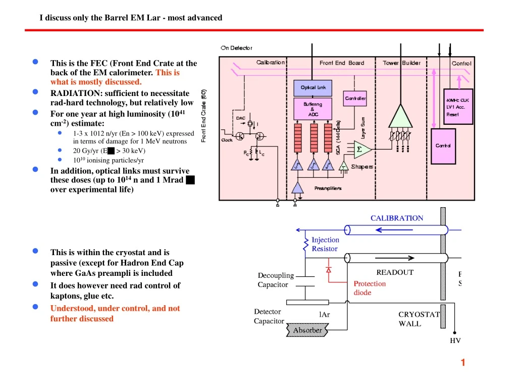
This is the FEC (Front End Crate at the back of the EM calorimeter. This is what is mostly discussed. RADIATION: sufficient to necessitate rad-hard technology, but relatively low For one year at high luminosity (1041 cm-2) estimate: 1-3 x 10¹² n/yr (En > 100 keV) expressed in terms of damage for 1 MeV neutrons 20 Gy/yr (Eg > 30 keV) 1010 ionising particles/yr In addition, optical links must survive these doses (up to 1014 n and 1 Mrad g over experimental life) This is within the cryostat and is passive (except for Hadron End Cap where GaAs preampli is included It does however need rad control of kaptons, glue etc. Understood, under control, and not further discussed I discuss only the Barrel EM Lar - most advanced 1
This is connected to FEC by an optical link. It is OUTSIDE the radiation zone (we are building the RODs). Final production prototypes of all (I think) units exist and not time critical. A fully equipped back-end crate will be used in the Front-End system test foreseen end 2003 at BNL. Not further discussed. 2
FE Crate • Full functionality was demonstrated by Module 0 electronics (~6k channels), used in testbeam measurements of CAL modules for past several years • Due to schedule constraints, was not required to be radiation tolerant • Three main blocks - calibration, analog shaping etc, • Results in a NIM paper that I will give to you, results summarised in part I for what concerns electronics • First rad-tol prototypes of the various boards are now available • A system test (1/2 crate) is last step before launching full production • System test to be completed before end of 2003, with production to be launched beginning of 2004 (installation in ATLAS pit starts 11/2004) 3
Specifications and properties of FEB 190 K channels, current preamplification with Ipeak ~ 2.8 mA/GeV. Three types of preamplifier are used, depending on the input impedance (20pF - 3 nF). It is a 4-channel hybrid design. Pulse shape triangular with rise time of a few nsec, and decay time typically in range ~ 450 nsec depending on impedance - subsequent shaping. Shaper is a CR-RC circuit with t~13 ns. After shaping the signal is sampled and stored in SCA pipeline chip at 40 MHz. Level 1 trigger rate is 75 kHz, resulting in need for a 2.5 msec analog pipeline of the front end chip (SCA). This is all followed by ADC (5 MHz). They aim for calibration circuitry with uniformity and precision < 0.25%. 3 readout layers plus preshower layer - result is typically 10-100 cells hit by a shower; for this reason coherent noise must be kept low (<5% of incoherent noise) 38 FEB’s were made Test bench performance of FEB’s for the 3 different preamp types Average noise C=0.3 nF and C = 1 nF 1.1 Radsoft Module 0 4
Specifications and properties of CAL board 10 CAL boards were made, each with 64 channels Provide a signal like ionisation signal over full dynamic range Uniformity needed to 0.25% Test bench performance of CAL boards output shows a rise time of ~ 1 nsec and exponential decay On the top of the signal there is a small parasitic charge which results in an integral nonlinearity of ~0.1% for low and medium gain, a bit worse for high gain\ Pulse uniformity measured to be 0.2% due mainly to different cable lengths to input, after correction rms is 0.11% Noise and gain when connected to module 0 Regular calibrations made when fully connected to Module 0 in test beam. Non-linearity better than 1% over full dynamic range, and stability of gain over run period a few parts per mil. Coherent noise on each FEB ~5% of incoherent noise. The rms noise in high gain is ~ 10 MeV (preshower), 11-13 MeV (front), 28-31 MeV (middle) and 21-28 MeV (back). For an typical electron cluster at n=0.26 the total noise for high (medium) gain is 140 (260) MeV, of which 95% (80%) is incoherent. There were some problems with crosstalk, but now studied and solved - a question also for radhard case - worst effect is between electrodes (max 4.1%) Measured S/N for muons is 7.11±0.07 1.2 Radsoft Module 0 • Result: • - specs reached in rad soft prototype • has to be repeated with the “production • rad hard electronics NB: A similar full test has been made with the HEC system 5
The following slides are based on the talk of John Parsons at the last LHCC (July 2) FEB boards now exist in rad-hard technology, and also CAL, TRIG and CNTL boards. 10 FEB boards have been made and 2 boards have been populated. The main problem appears to be the Voltage Regulator A full system test of a FEC crate has yet to be made. This will imply 20 FEB boards if I understand. The system test is being prepared in BNL and was foreseen this summer. It is now hoped for end 2003 or early 2004. 2.0 RADHARD ELECTRONICS 6
2.1 Overview of Front End (FE) Component Issues • Move to radhard FE electronics required development and qualification of a total of 15 custom rad-tol ASICS (in various technologies): • 10 in DMILL • 4 in DSM (using rad-tol standard cell library) - deep sub-micron • 1 in AMS BiCMOS • All custom ASICs are available, or are in production • A limited number of COTs are needed (ADC, op-amps, GLink, line driver) • Extensive radiation qualification procedures performed • All production COTs have been purchased and qualified, except for ADC for which common ATLAS/CMS/LHCb order is to be signed very soon • LAr FE, and particularly the FEB boards, has extensive needs for voltage regulatoprs Vregs (both + and -) • ST (Thompson) contracted by CERN to develop rad-tol Vregs for general LHC use • Positive Vregs (L4913) successfully developed, and production quantities avail. • Negative Vreg (L7913) design continues to have technical problems, and is significantly impacting our FE electronics development - this is a major problem. 7
2.2 LAr DMILL Chip Status - components for CAL, FEB etc boards • LAr has 3 different DMILL wafer sets: • - Temic DMILL process stops at end of 2003, and this has major impact on Lar schedule, as well as SCT etc - a real problem • DMILL process is less radiation tolerant than originally foreseen - not a problem for Lar, but a big problem for SCT etc 1. SCA (pipeline) production (200 wafers) • robotic testing should be finished TODAY! (> 85k SCA chips tested) • there are enough good SCA chips 2. Analog wafers (12 wafers of BiMUX, opamp) • wafers received in Jan. 2003 • closure of ASAT France has led to lengthy (> 3 mo.) delays in packaging • tests on chips from first wafer have reasonable yield; remaining 11 sent for pkging 3. Digital wafers (27 wafers of SPAC, CALogic, CONFIG, SMUX, DAC) • wafer processing underway, with delivery scheduled for August 2003 • failure of ATMEL to deliver would have far-reaching consequences • DSM replacements would need to be developed • Significant re-design would be needed for ALL boards • DMILL situation is being monitored closely 8
2.2 cont LAr DMILL Chip Status - components for CAL, FEB etc boards • Rad levels of all tests ….. Type of radiation Expected Tested TID 5 kRad 52 - 175 kRad NIEL 1.6 1012 n/cm2 1.6 1013 n/cm2 SEE 7.7 1011 h/cm2 7.7 1012 h/cm2 • Rad test of DMILL Configuration Controller • Tested to 10 x expected radiation - significant degradation, but meets specifications. • No latchup detected, 90% CL < 1 per 2.6 days. This is overestimate since only used in setup. 9
2.3 LAr Deep Submicron (DSM) Chip Status - components for CAL, FEB etc boards • 3 LAr-specific DSM ASICs (SCAC, GainSel, CLKFO) • MPW runs used to demonstrate design, rad. tolerance • PRR passed in September 2002 • Enough devices available for short-term needs • Engineering run (2 wafers) delivered April 22 • Goals: produce final masks, determine yield, re-verify rad. tolerance • Due to pkg’ing delays, we still have not received the chips (expected mid-May) • We have postponed (twice!) the irrad. tests, now re-scheduled for July 19/20 • Once eng. run tests done, submit production order (45 wafers) • Still in time for FEB production needs,but need to pay attention to schedule • Rad test of DSM SCA controller • Tested to 10 x expected radiation - no degradation of performance and for full Lar barrel expect 1 latchup per 6.9 minutes (97-99% recoverable by redundancy, includes factror 10 safety) • Rad test of Commercial Triple Line Receiver • Tested to 10 x expected radiation - no degradation of performance and for full Lar barrel expect with safety factor <130 latchups at 90% CL. • Rad test of DSM Gain Selector • Tested to 10 x expected radiation - no degradation of performance and for full Lar barrel expect with safety factor 1 latchup per 3.1 hours (most redundant) Further radiation tests of the DSM components and custom components such as line receivers etc are if I understand being made July/August 2003. No show stoppers expected. 10
2.4 Radhard Voltage Regulator Status • ST was contracted by CERN to develop rad-tol Vregs (both + and -) • Positive Vreg (L4913) successfully developed and now available in quantity • have been using these devices since early 2002 • have received the full production quantity • Negative Vreg (L7913) has gone through several iterations, but continues to suffer from technical problems • JQ3 (04/2002) – non-functional • JQ4 (11/2002) – functional, but tends to oscillate • JQ5 (06/2003) – more stable, but suffers from thermal instability for large loads • L7913 problems have significantly delayed FE system test, which was originally scheduled for Summer 2002 • have tried hard, but not succeeded, in finding a suitable alternate solution • To minimize delay, have proceeded with design of boards using L7913, and tested them as best as possible (eg. with less-than-perfect L7913 samples, commercial Vregs, etc.) to be ready when L7913 becomes available • On June 24, 10 JQ5 samples were received and immediately added to existing 2 FEB prototypes • Preliminary tests verify improved stability compared to JQ4. • It is possible the JQ5 thermal problem would not be serious in our application • Plan to proceed with FE system test using JQ5, and implement JQ6 when they arrive (October 2003) • L7913 continues to represent significant risk to FE electronics development 11
2.5 Radiation Tolerant Front End Board Front End Board (FEB) : 1524 boards @ 128 ch in final system Component rad tests being made (see slides), unclear to me whether a full board will be radiated 12
2.6 Radiation Tolerant Calibration Board Calibration : 116 boards @ 128 ch 13
2.7 Radiation Tolerant Controller and Trigger Boards Controller : 116 boards Tower builder(TBB) : 120 boards @ 32 ch 14
2.8 Radiation Tolerant LV Power Supply • 300 VDC brought to area of TileCal “fingers” • FE crate requires 7 different DC voltages • Technical solution with DC-DC convertors was developed through an extended R&D and radiation qualification program • Produce modules with specially chosen components • Provide redundancy due to SEU-burnout concerns • Contract awarded for production of 2 prototypes • Significant delays incurred in finalizing services, requirements • Prototype delivery now scheduled for end August 2003 • FE crate will have to start with other LVPS • Have only 60 days after prototype delivery to exercise option for full production • Need to follow schedule very closely 15
2.9 Front End Crate (FEC) Test • Before proceeding to PRR and then production for the various FEC boards, plan a system test with all boards together, filling the “basic unit” of ½ FEC • FEC test setup will include: • “dummy” calorimeter loads • cables (det FT baseplane) • FE crate, including: • PWR/signal distribution • water cooling • Prototype LV power supply • Controller, CALIB, TTB boards • From 1 FEB,to 14 FEBs • Prototype Monitor boards • DCS monitoring with ELMB • VME-based TTC + SPACMaster • Temporary VME-based readout for up to 16 FEBs 16
2.10 FE Crate System Test in Preparation • Setup prepared with 1 FEB, commercial PS • Plan to now produce remaining FEBs, populated with new JQ5 Vreg samples • Start FEC test in August • Identify and perform tests which can be done before final Vreg, PS solutions are available • Move to final power devices as available: • Prototype LVPS in September • JQ6 Vreg samples in October • Aim for FEC boards’ PRRs in late November • FEC test schedule is very tight • Neg. Vreg and LVPS continue to present significant risks 17
3.0 Summary • Final prototypes of both FE and BE electronics boards are now available • FE and BE system tests are scheduled to be completed by end of 2003 • Electronics production to start in early 2004 • Installation in ATLAS pit to start by 11/2004 • Main concerns continue to be: • Negative Vreg • Need to determine if either JQ6 or JQ5 version is suitable for production (10/03) • Rad-tol LVPS • Need to test prototype and launch production (10/03) • DMILL • Need successful delivery of LAr DMILL Digital Wafers (08/03) 18