Download

1 / 56
560 likes | 776 Views
Introduction to Internet Protocol (IP) Version 4 and Version 6. OSI Stack & TCP/IP Architecture. Principles of the Internet. Edge vs. core (end-systems vs. routers) Dumb network Intelligence at the end-systems Different communication paradigms Connection oriented vs. connection less

E N D
Introduction to Internet Protocol (IP) Version 4 and Version 6
Principles of the Internet • Edge vs. core (end-systems vs. routers) • Dumb network • Intelligence at the end-systems • Different communication paradigms • Connection oriented vs. connection less • Packet vs. circuit switching • Layered System • Network of collaborating networks
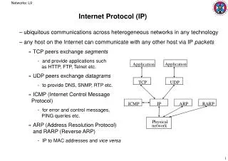
The network edge • end systems (hosts): • run application programs • e.g., WWW, email • at “edge of network” • client/server model: • client host requests, receives service from server • e.g., WWW client (browser)/server; email client/server • peer-peer model: • host interaction symmetric e.g.: teleconferencing
Network edge: connection-oriented service • Goal: data transfer between end sys. • handshaking: setup (prepare for) data transfer ahead of time • Hello, hello back human protocol • set up “state” in two communicating hosts • TCP - Transmission Control Protocol • Internet’s connection-oriented service TCP service [RFC 793] reliable, in-order byte-stream data transfer loss: acknowledgements and retransmissions flow control: sender won’t overwhelm receiver congestion control: senders “slow down sending rate” when network congested
Network edge: connectionless service • Goal: data transfer between end systems • UDP - User Datagram Protocol [RFC 768]: Internet’s connectionless service • unreliable data transfer • no flow control • no congestion control
Protocol “Layers” • Networks are complex! • many “pieces”: • hosts • routers • links of various media • applications • protocols • hardware, software Question: Is there any hope of organizing structure of network? Or at least in our discussion of networks?
The unifying effect of the network layer • Define a protocol that works in the same way with any underlying network • Call it the network layer (e.g. IP) • IP routers operate at the network layer • IP over anything • Anything over IP
Why layering? • Dealing with complex systems: • explicit structure allows identification, relationship of complex system’s pieces • layered reference model for discussion • Modularisation eases maintenance, updating of system • change of implementation of layer’s service transparent to rest of system • e.g., change in gate procedure does not affect rest of system
FTP DNS Video SMTP HTTP Audio Telnet TCP UDP RTP IP ATM Optics ADSL 3G PPP Satellite Ethernet The IP Hourglass Model Application layer Transport layer Network layer Physical and Data link layer
Application 7 Presentation 6 Session 5 Transport 4 Network 3 Data Link 2 Physical 1 The OSI Model Upper Layers Application oriented “End-to-End”-Layers Lower Layers Network oriented “Hop-by-hop” layers
OSI Model and the Internet • Internet protocols are not directly based on the OSI model • However, we do often use the OSI numbering system. You should at least remember these: • Layer 7: Application • Layer 4: Transport (e.g. TCP, UDP) • Layer 3: Network (IP) • Layer 2: Data link • Layer 1: Physical
Application Application TCP or UDP TCP or UDP IP IP IP IP Link Link Link Link Link Link Physical Physical Physical Layer Interaction:TCP/IP Model End to end Hop by hop Router Host Host Router
End-to-end layers • Upper layers are “end-to-end” • Applications at the two ends behave as if they can talk directly to each other • They do not concern themselves with the details of what happens in between
Hop-by-hop layers • At the lower layers, devices share access to the same physical medium • Devices communicate directly with each other • The network layer (IP) has some knowledge of how many small networks are interconnected to make a large internet • Information moves one hop at a time, getting closer to the destination at each hop
Application Application TCP or UDP TCP or UDP IP IP IP IP Link Link Link Link Link Link Physical Physical Physical Layer Interaction:TCP/IP Model Router Host Host Router
Application Application TCP or UDP TCP or UDP IP IP IP IP Link Link Link Link Link Link Physical Physical Physical Layer Interaction:The Application Layer Applications behave as if they can talk to each other, but in reality the application at each side talks to the TCP or UDP service below it. The application layer doesn't care about what happens at the lower layers, provided the transport layer carries the application's data safely from end to end. Router Host Host Router
Application Application TCP or UDP TCP or UDP IP IP IP IP Link Link Link Link Link Link Physical Physical Physical Layer Interaction:The Transport Layer The transport layer instances at the two ends act as if they are talking to each other, but in reality they are each talking to the IP layer below it. The transport layer doesn't care about what the application layer is doing above it. The transport layer doesn't care what happens in the IP layer or below, as long as the IP layer can move datagrams from one side to the other. Router Host Host Router
Application Application TCP or UDP TCP or UDP IP IP IP IP Link Link Link Link Link Link Physical Physical Physical Layer Interaction:The Network Layer (IP) The IP layer has to know a lot about the topology of the network (which host is connected to which router, which routers are connected to each other), but it doesn't care about what happens at the upper layers. The IP layer works forwards messages hop by hop from one side to the other side. Router Host Host Router
Application Application TCP or UDP TCP or UDP IP IP IP IP Link Link Link Link Link Link Physical Physical Physical Layer Interaction:Link and Physical Layers The link layer doesn't care what happens above it, but it is very closely tied to the physical layer below it. All links are independent of each other, and have no way of communicating with each other. Router Host Host Router
data application transport network link physical network link physical application transport network link physical data application transport network link physical application transport network link physical Layering: physical communication
Frame, Datagram, Segment, Packet • Different names for packets at different layers • Ethernet (link layer) frame • IP (network layer) datagram • TCP (transport layer) segment • Terminology is not strictly followed • we often just use the term “packet” at any layer
Encapsulation & Decapsulation • Lower layers add headers (and sometimes trailers) to data from higher layers Application Data Transport Header Transport Layer Data Network Header Network Layer Data Network Header Header Data Data Link Trailer Header Link Layer Data Data Link Header Header Header Data Trailer
Type Preamble Dest Source Data CRC Layer 2 - Ethernet frame • Destination and source are 48-bit MAC addresses (e.g., 00:26:4a:18:f6:aa) • Type 0x0800 means that the “data” portion of the Ethernet frame contains an IPv4 datagram. Type 0x0806 for ARP. Type 0x86DD for IPv6. • “Data” part of layer 2 frame contains a layer 3 datagram. 6 bytes 6 bytes 2 bytes 46 to 1500 bytes 4 bytes
Version IHL Total Length Diff Services Identification Flags Fragment Offset Time to Live Protocol Header Checksum Source Address (32-bit IPv4 address) Destination Address (32-bit IPv4 address) Options Padding Data (contains layer 4 segment) Layer 3 - IPv4 datagram Version = 4If no options, IHL = 5Source and Destination are 32-bit IPv4 addresses • Protocol = 6 means data portion contains a TCP segment. Protocol = 17 means UDP.
Source Port Destination Port Sequence Number Acknowledgement Number Data Offset Reserved URG ACK EOL RST SYN FIN Window Checksum Urgent Pointer Options Padding Data (contains application data) Layer 4 - TCP segment • Source and Destination are 16-bit TCP port numbers (IP addresses are implied by the IP header) • If no options, Data Offset = 5 (which means 20 octets)
Purpose of an IP address • Unique Identification of: • Source • How would the recipient know where the message came from? • How would you know who hacked into your network (network/data security) • Destination • How would you send data to other network • Network Independent Format • IP over anything
Purpose of an IP Address Identifies a machine’s connection to a network • Uniquely assigned in a hierarchical format • IANA (Internet Assigned Number Authority) • IANA to RIRs (AfriNIC, ARIN, RIPE, APNIC, LACNIC) • RIR to ISPs and large organisations • ISP or company IT department to end users • IPv4 uses unique 32-bit addresses • IPv6 uses unique 128-bit addresses
133 27 162 125 10000101 00011011 10100010 01111101 85 1B A2 7D Basic Structure of an IPv4 Address • 32 bit number (4 octet number):(e.g. 133.27.162.125) • Decimal Representation: • Binary Representation: • Hexadecimal Representation:
Addressing in Internetworks • The problem we have • More than one physical network • Different Locations • Larger number of hosts/computer systems • Need a way of numbering them all • We use a structured numbering system • Hosts that are connected to the same physical network may have “similar” IP addresses
Network part and Host part • Remember IPv4 address is 32 bits • Divide it into a “network part” and “host part” • “network part” of the address identifies which network in the internetwork (e.g. the Internet) • “host part” identifies host on that network • Hosts or routers connected to the same link-layer network will have IP addresses with the same network part, but different host part. • Host part contains enough bits to address all hosts on that subnet; e.g. 8 bits allows 256 addresses
Dividing an address • Hierarchical Division in IP Address: • Network Part (or Prefix) – high order bits (left) • describes which physical network • Host Part – low order bits (right) • describes which host on that network • Boundary can be anywhere • Boundaries are chosen according to number of hosts required Host Part Network Part
Network Masks • “Network Masks” help define which bits describe the Network Part and which for the Host Part • Different Representations: • decimal dot notation: 255.255.224.0 • binary: 11111111 11111111 11100000 00000000 • hexadecimal: 0xFFFFE000 • number of network bits: /19 • count the 1's in the binary representation • Above examples all mean the same: 19 bits for the Network Part and 13 bits for the Host Part
1000 1001 1001 1110 0000 0000 1100 0110 1000 0110 0000 0000 0000 0000 1100 1101 0010 0101 1100 0001 10 00 0000 Example Prefixes • 137.158.128.0/17 (netmask 255.255.128.0) • 198.134.0.0/16 (netmask 255.255.0.0) • 205.37.193.128/26 (netmask 255.255.255.192) 1111 1111 1111 1111 1 000 0000 0000 0000 1 000 0000 1111 1111 1111 1111 0000 0000 0000 0000 1111 1111 1111 1111 1111 1111 11 00 0000
Special Addresses • All 0’s in host part: Represents Network • e.g. 193.0.0.0/24 • e.g. 138.37.64.0/18 • All 1’s in host part: Broadcast • e.g. 193.0.0.255 (prefix 193.0.0.0/24) • e.g. 138.37.127.255 (prefix 138.37.64.0/18) • 127.0.0.0/8: Loopback address (127.0.0.1) • 0.0.0.0: For various special purposes
Ancient History: • A classful network naturally “implied” a prefix-length or netmask: • Class A: prefix length /8 (netmask 255.0.0.0) • Class B: prefix length /16 (netmask 255.255.0.0) • Class C: prefix length /24 (netmask 255.255.255.0) • Modern (classless) routed networks rather have explicit prefix-lengths or netmasks. • So ideally you can't just look at an IP address and tell what its prefix-length or netmask should be. • Protocol configurations in this case also need explicit netmask or prefix length.
Post-1994 era of classless addressing • Class A, Class B, Class C terminology and restrictions are now of historical interest only • Obsolete since 1994 • Internet routing and address management today is classless • CIDR = Classless Inter-Domain Routing • Routing does not assume that former class A, B, C addresses imply prefix lengths of /8, /16, /24 • VLSM = Variable-Length Subnet Masks • Routing does not assume that all subnets are the same size
Classless addressing example • An ISP gets a large block of addresses • e.g., a /16 prefix, or 65536 separate addresses • Assign smaller blocks to customers • e.g., a /24 prefix (256 addresses) to one customer, and a /28 prefix (16 addresses) to another customer (and some space left over for other customers) • An organisation that gets a /24 prefix from their ISP divides it into smaller blocks • e.g. a /27 prefix (32 addresses) for one department, and a /28 prefix (16 addresses) for another department (and some space left over for other internal networks)
Classless addressing exercise • Consider the address block 133.27.162.0/24 • Allocate 5 separate /28 blocks, one /27 block, and one /30 block • What are the IP addresses of each block allocated above? • In prefix length notation • Netmasks in decimal • IP address ranges • What blocks are still available (not yet allocated)? • How big is the largest available block?
IPv6 Addressing IP Addresses Continues
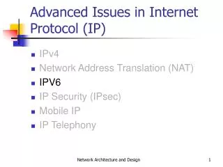
IP version 6 • IPv6 designed as successor to IPv4 • Expanded address space • Address length quadrupled to 16 bytes (128 bits) • Header Format Simplification • Fixed length, optional headers are daisy-chained • No checksum at the IP network layer • No hop-by-hop fragmentation • Path MTU discovery • 64 bits aligned fields in the header • Authentication and Privacy Capabilities • IPsec is mandated • No more broadcast
Version Traffic Class Flow Label Version IHL Type of Service Total Length Identification Flags Fragment Offset Payload Length Next Header Hop Limit Time to Live Protocol Header Checksum Source Address Source Address Destination Address Options Padding Destination Address IPv4 and IPv6 Header Comparison IPv6 Header IPv4 Header Legend Field’s name kept from IPv4 to IPv6 Fields not kept in IPv6 Name and position changed in IPv6 New field in IPv6
Larger Address Space IPv4 = 32 bits IPv6 = 128 bits • IPv4 • 32 bits • = 4,294,967,296 possible addressable devices • IPv6 • 128 bits: 4 times the size in bits • = 3.4 x 1038 possible addressable devices • = 340,282,366,920,938,463,463,374,607,431,768,211,456 • 5 x 1028 addresses per person on the planet
IPv6 Address Representation • 16 bit fields in case insensitive colon hexadecimal representation • 2031:0000:130F:0000:0000:09C0:876A:130B • Leading zeros in a field are optional: • 2031:0:130F:0:0:9C0:876A:130B • Successive fields of 0 represented as ::, but only once in an address: • 2031:0:130F::9C0:876A:130B is ok • 2031::130F::9C0:876A:130B is NOT ok (two “::”) • 0:0:0:0:0:0:0:1 ::1 (loopback address) • 0:0:0:0:0:0:0:0 :: (unspecified address)
IPv6 Address Representation • In a URL, it is enclosed in brackets (RFC3986) • http://[2001:db8:4f3a::206:ae14]:8080/index.html • Complicated for typical users • This is done mostly for diagnostic purposes • Use fully qualified domain names (FQDN) instead of this • Prefix Representation • Representation of prefix is same as for IPv4 CIDR • Address and then prefix length, with slash separator • IPv4 address: • 198.10.0.0/16 • IPv6 address: • 2001:db8:12::/40
Type Binary Hex Unspecified 0000…0000 ::/128 Loopback 0000…0001 ::1/128 Global Unicast Address 0010 ... 2000::/3 Link Local Unicast Address 1111 1110 10... FE80::/10 Unique Local Unicast Address 1111 1100 ... 1111 1101 ... FC00::/7 Multicast Address 1111 1111 ... FF00::/8 IPv6 Addressing
IPv6 Global Unicast Addresses • IPv6 Global Unicast addresses are: • Addresses for generic use of IPv6 • Hierarchical structure intended to simplify aggregation Provider Site Host 48 bits 16 bits 64 bits Global Routing Prefix Subnet-id Interface ID 001
IPv6 Address Allocation • The allocation process is: • The IANA is allocating out of 2000::/3 for initial IPv6 unicast use • Each registry gets a /12 prefix from the IANA • Registry allocates a /32 prefix (or larger) to an IPv6 ISP • ISPs usually allocate a /48 prefix to each end customer /12 /48 /64 /32 2000 0db8 Interface ID Registry ISP prefix Site prefix LAN prefix
IPv6 Addressing Scope • 64 bits used for the interface ID • Possibility of 264 hosts on one network LAN • Arrangement to accommodate MAC addresses within the IPv6 address • 16 bits used for the end site • Possibility of 216 networks at each end-site • 65536 subnets