Download
1 / 31
310 likes | 525 Views
CERN-LAr1_ND meeting– 17 th February 2014. CENF target station and secondary beam design. M. Calviani (CERN) on behalf of the CENF Secondary Beam Working Group.

E N D
CERN-LAr1_ND meeting– 17thFebruary 2014 CENF target station and secondary beam design M. Calviani (CERN) on behalf of the CENF Secondary Beam Working Group With contributions from M. Nessi, R. Steerenberg, A. Ferrari, P. Sala, V. Venturi, R. Losito, A. Perillo-Marcone, C. Strabel, H. Vincke, J. Osborne, M. Battistin, S. Girod, K. Kershaw, I. Efthymiopoulos, M. De Pablos, L. Faisandel, M. Archambault, F. Valentini, S. Hutchins, P. Vojtyla, F. Malacrida
Outlook M. Calviani - CENF Target station and secondary beam design - CENF-LAr1-ND meeting • Design of the CENF target facility and secondary beam • Target R&D • Cooling and ventilation design • Thermo mechanical aspects • Radioprotection and environmental releases • Conclusions
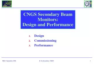
Target areas at CERN Antiproton target WANF & CNGS n_TOF (neutrons) beam TCC2 M. Calviani - CENF Target station and secondary beam design - CENF-LAr1-ND meeting • CERN target areas are generally halls, pits or long tunnels, far from the access points • Air has enough time to decay and stray radiation is not a problem for the public • Neutrino ones are generally deep in the molasse
CENF target facility M. Calviani - CENF Target station and secondary beam design - CENF-LAr1-ND meeting • Due to the shallow depth of the beam line (~14 meters), a target area approach based on long tunnels (i.e. CNGS, WANF, etc.) is not applicable • A multi-compartment solution similar to T2K/NuMI has been therefore developed, taking into account the specificities of CERN • The proposed technical solutions and methods for the target station design are adaptable for other similar projects at CERN
M. Calviani - CENF Target station and secondary beam design - CENF-LAr1-ND meeting
Hadron absorber and m pits Target cavern and hall Decay pipe M. Calviani - CENF Target station and secondary beam design - CENF-LAr1-ND meeting • Beam line under He, to avoid NOx formation and to reduce air activation • Angle, distance and depth optimised to keep dose rate in EHN1 <1 mSv/h and to allow ND at 460 m from target • Target shielding adapted to H*(10) <15 mSv/h • Air treatment and water recuperation • Double muon pits to provide info on alignment, target “health” and m flux for n flux predictions
Target area transversal cross-cut Hadron absorber / muon pits longitudinal cut M. Calviani - CENF Target station and secondary beam design - CENF-LAr1-ND meeting • Drawings essentially ready for CE tender
Importance of a double m pit • Energy distribution of parents p/K, generating m arriving in pit#1 and pit#2 • Pit1 sensitive to low energy m M. Calviani - CENF Target station and secondary beam design - CENF-LAr1-ND meeting • “thermalized” m spectrum in both pits • Impossible to know from which p these m come from • Shape remains the same as a function of depth
Integration of target trench, 3x3 m2 • Matches the DP diameter 2.4 m ONGOING DESIGN 18 m M. Calviani - CENF Target station and secondary beam design - CENF-LAr1-ND meeting • Handling system design: • 40 ton + 15 ton crane, redundant systems foreseen • Pure vertical movement system as baseline, respecting ITER Remote Handling Code of Practice • Support module fixed during operation (under design)
Horn/Reflector support module PRELIMINARY M. Calviani - CENF Target station and secondary beam design - CENF-LAr1-ND meeting
Neutrino beam characteristics Perfect focus within 1 rad Best configuration Initial configuration • Baseline DP radius of 150 cm M. Calviani - CENF Target station and secondary beam design - CENF-LAr1-ND meeting • 5 GeV pion focusing – central nm energy ~1.8 GeV • Target inside horn, followed by reflector
CENF target R&D M. Calviani - CENF Target station and secondary beam design - CENF-LAr1-ND meeting • 100 cm long, 12 mm Ø challenging design • ~2 kW dep. power, He-cooled graphite PT2020 • Graphite to be maintained around 600-700 K • Minimize mechanical properties change due to radiation effects • Baseline fully inserted inside horn • Complex design due to design IC Ø (24 mm – 30 mm) • Need low-Z but very rigid material to contain the graphite
Thermal compressive stress: <2 MPa • Max graph. radial expansion: ~120 mm • Stresses due to pressure on Be structure (@20bar): 25 MPa(max) M. Calviani - CENF Target station and secondary beam design - CENF-LAr1-ND meeting
Ventilation system design • CENF ventilation design respects ISO17873:2004* • Pressure cascade of multi-compartments (from -60 to -220 Pa) • Flow rate: between 1 and 5 volumes/h • HEPA filters (F8+H14) • Low humidity control in the service pit (*) adapted for nuclear instalallation other than nuclear reactors M. Calviani - CENF Target station and secondary beam design - CENF-LAr1-ND meeting
Ventilation system design Surface hall – partial recirculation Underground areas (limited activation) – direct flow (dry air) Service pit (high activation) – recirculation M. Calviani - CENF Target station and secondary beam design - CENF-LAr1-ND meeting
Main exhaust stack Delay line on the service pit extraction Extraction units for underground areas Evaporator for rising systems and water collection Service pit circulation and DP cooling M. Calviani - CENF Target station and secondary beam design - CENF-LAr1-ND meeting
Summary of structural elements cooling DP steel/concrete air (or He-cooled) Water cooling of lateral shielding Helium forced circulation inside the He-vessel Water cooling of DP iron collar Water cooled hadron absorber M. Calviani - CENF Target station and secondary beam design - CENF-LAr1-ND meeting
He-vessel + steel shielding cooling OUTLET BEAM horn reflector INLET INLET • Inlet @horn and reflector striplines (~0.7 m/s) • Outlet symmetric upstream the He-vessel • ~5 m/s, 6000 m3/h (DT~10 K) Steel blocks segmented in order to allow the flow of He M. Calviani - CENF Target station and secondary beam design - CENF-LAr1-ND meeting • Cooling of steel blocks and He-vessel via forced He-flow (~30 kW)
Max He-vessel structure temperature at ~50 °C Max steel blocks temperature at ~35 °C M. Calviani - CENF Target station and secondary beam design - CENF-LAr1-ND meeting
Max shielding temperature <40 °C BEAM BEAM M. Calviani - CENF Target station and secondary beam design - CENF-LAr1-ND meeting • Water cooled shielding steel blocks: • 5 pipes, in contact with lateral shielding (0.5 m/s at 25 °C) • Bottom layer cooled by conduction with lateral steel blocks
Decay pipe cooling • DP steel/concrete is air (or He) cooled (~80 kW) • 8 pipes (x2), Ø=20 cm • Total air flow 8000 m3/h (x2 for He) Cool line (air/He) Return loop (air/He) • DT ~15 °C • Max velocity 11 m/s (16 m/s for He) • DP ~690 Pa (320 Pa for He) • Max temperature ~75 °C on steel wall • Concrete external temperature (@3.5 m) ~32 °C M. Calviani - CENF Target station and secondary beam design - CENF-LAr1-ND meeting
Hadron absorber cooling • Graphite (Al) core, cooled by two water-cooled Al sinks • Steel shielding (for muon and RP) 6 m 5 m steel Al 6.9 m graphite graphite 3 m 3 m Al Steel M. Calviani - CENF Target station and secondary beam design - CENF-LAr1-ND meeting • Basic design is a CNGS-like dump (total power ~75 kW)
Radioprotection M. Calviani - CENF Target station and secondary beam design - CENF-LAr1-ND meeting • Radioprotection pivotal aspect for the design of (any) installation • Additional complexity due to the proximity to CERN fence (~70 meters) • Analysis performed: • Air activation max annual releases <10 TBq/y • High energy hadrons and cumulated dose • Waste zoning • Prompt doseand soil activation • Residual dose rates
M. Calviani - CENF Target station and secondary beam design - CENF-LAr1-ND meeting • Prompt dose in accessible areas during operation <15 mSv/h • Residual dose rate in service pit (above He-vessel), 0.1 – 1 mSv/h • Yearly ambient dose rate at CERN fence is ≤5 mSv/y
M. Calviani - CENF Target station and secondary beam design - CENF-LAr1-ND meeting
M. Calviani - CENF Target station and secondary beam design - CENF-LAr1-ND meeting
Environmental releases 11C, 13N, 14, 15O, 41Ar: Dominate the exposure • Expected maximum dosimetric impact <0.05 mSv/y M. Calviani - CENF Target station and secondary beam design - CENF-LAr1-ND meeting • A complex model has been developed at CERN for this project in order to estimate the annual releases from the various subsystems • Key aspect is the ventilation system design
Environmental releases M. Calviani - CENF Target station and secondary beam design - CENF-LAr1-ND meeting • With the designed ventilation system, the radioactive emissions from the target facility are not a show-stopper • Recirculation in the service pit is preferred (removal of 7Be and P) • In case of an air-filled target chamber production of radionuclides would be at least 10x larger • Limited – contributions from the water evaporator system (3H) • Collection of humidity from underground areas and potentially contaminated drains
Preliminary risk analysis M. Calviani - CENF Target station and secondary beam design - CENF-LAr1-ND meeting • As a part of the project, a safety study has been launched • Identification of hazardand risks reduction for the CENF target facility • Analyse in detail possible accident scenarios related to every hazard • Evaluate the role in the risk reduction of every protection barriers • Document the Safety Qualification Requirements for the safety system implementation (part of the design study)
Summary M. Calviani - CENF Target station and secondary beam design - CENF-LAr1-ND meeting • A sound technical design for a new CERN neutrino beam line is being developed • Facility designed for a beam power of 200 kW (with margins), but the design is scalable for higher power • A design study report will be released during the course of 2014 • The design choices could be applicable also for other target facilities proposed at CERN using SPS beam @NA