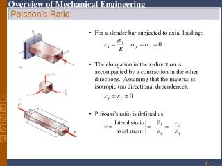
Poisson’s Ratio
For a slender bar subjected to axial loading:. The elongation in the x-direction is accompanied by a contraction in the other directions. Assuming that the material is isotropic (no directional dependence),. Poisson’s ratio is defined as. Poisson’s Ratio. With these restrictions:.

Poisson’s Ratio
E N D
Presentation Transcript
For a slender bar subjected to axial loading: • The elongation in the x-direction is accompanied by a contraction in the other directions. Assuming that the material is isotropic (no directional dependence), • Poisson’s ratio is defined as Poisson’s Ratio
With these restrictions: Generalized Hooke’s Law • For an element subjected to multi-axial loading, the normal strain components resulting from the stress components may be determined from the principle of superposition. This requires: • 1) strain is linearly related to stress2) deformations are small
(change in volume)/(unstressed state volume) = e • For element subjected to uniform hydrostatic pressure, • Subjected to uniform pressure, dilatation must be negative (k > 0), therefore Dilatation: Bulk Modulus
A cubic element subjected to a shear stress will deform into a rhomboid. The corresponding shear strain is quantified in terms of the change in angle between the sides, • A plot of shear stress vs. shear strain is similar to the previous plots of normal stress vs. normal strain except that the strength values are approximately half. For small strains, where G is the modulus of rigidity or shear modulus. Shearing Strain
Example 2.10 • SOLUTION: • Determine the average angular deformation or shearing strain of the block (no slip between plate and material) • Apply Hooke’s law for shearing stress and strain to find the corresponding shearing stress. A rectangular block of material with modulus of rigidity G = 90 ksi is bonded to two rigid horizontal plates. The lower plate is fixed, while the upper plate is subjected to a horizontal force P. Knowing that the upper plate moves through 0.04 in. under the action of the force, determine a) the average shearing strain in the material, and b) the force P exerted on the plate. • Use the definition of shearing stress to find the force P.
Determine the average angular deformation or shearing strain of the block. • Apply Hooke’s law for shearing stress and strain to find the corresponding shearing stress. • Use the definition of shearing stress to find the force P.
Components of normal and shear strain are related, Relation Among E, n, and G • An axially loaded slender bar will elongate in the axial direction and contract in the transverse directions. • An initially cubic element oriented as in top figure will deform into a rectangular parallelepiped. The axial load produces a normal strain. • If the cubic element is oriented as in the bottom figure, it will deform into a rhombus. Axial load also results in a shear strain.
Sample Problem 2.5 • A circle of diameter d = 9 in. is scribed on an unstressed aluminum plate of thickness t = 3/4 in. Forces acting in the plane of the plate later cause normal stresses sx = 12 ksi and sz = 20 ksi. • For E = 10x106 psi and n = 1/3, determine the change in: • the length of diameter AB, • the length of diameter CD, • the thickness of the plate, and • the volume of the plate.
SOLUTION: • Apply the generalized Hooke’s Law to find the three components of normal strain. • Evaluate the deformation components. • Find the change in volume
Normal stresses and strains are related by Hooke’s Law but with directionally dependent moduli of elasticity (anisotropy), • Transverse contractions are related by directionally dependent values of Poisson’s ratio, e.g., Composite Materials • Fiber-reinforced composite materials are formed from lamina of fibers of graphite, glass, or polymers embedded in a resin matrix. • Materials with directionally dependent mechanical properties are anisotropic.
Saint-Venant’s Principle • Loads transmitted through rigid plates result in uniform distribution of stress and strain. • Concentrated loads result in large stresses in the vicinity of the load application point. • Stress and strain distributions become uniform at a relatively short distance from the load application points. • Saint-Venant’s Principle:Stress distribution may be assumed independent of the mode of load application except in the immediate vicinity of load application points.
Stress Concentration: Hole Discontinuities of cross section may result in high localized or concentrated stresses.
Example 2.12 • SOLUTION: • Determine the geometric ratios and find the stress concentration factor from Fig. 2.64b. Determine the largest axial load P that can be safely supported by a flat steel bar consisting of two portions, both 10 mm thick, and respectively 40 and 60 mm wide, connected by fillets of radius r = 8 mm. Assume an allowable normal stress of 165 MPa. • Find the allowable average normal stress using the material allowable normal stress and the stress concentration factor. • Apply the definition of normal stress to find the allowable load.
Determine the geometric ratios and find the stress concentration factor from Fig. 2.64b. • Find the allowable average normal stress using the material allowable normal stress and the stress concentration factor. • Apply the definition of normal stress to find the allowable load.
Analysis of plastic deformations is simplified by assuming an idealized elastoplastic material • Deformations of an elastoplastic material are divided into elastic and plastic ranges • Permanent deformations result from loading beyond the yield stress Elastoplastic Materials • Previous analyses based on assumption of linear stress-strain relationship, i.e., stresses below the yield stress • Assumption is good for brittle material which rupture without yielding • If the yield stress of ductile materials is exceeded, then plastic deformations occur
Maximum stress is equal to the yield stress at the maximum elastic loading • As the loading increases, the plastic region expands until the section is at a uniform stress equal to the yield stress Plastic Deformations • Elastic deformation while maximum stress is less than yield stress • At loadings above the maximum elastic load, a region of plastic deformations develop near the hole
Residual Stresses • When a single structural element is loaded uniformly beyond its yield stress and then unloaded, it is permanently deformed but all stresses disappear. This is not the general result. • Residual stresses will remain in a structure after loading and unloading if • only part of the structure undergoes plastic deformation • different parts of the structure undergo different plastic deformations • Residual stresses also result from the uneven heating or cooling of structures or structural elements