Download
1 / 26
260 likes | 438 Views
36 th Asilomar IEEE Conference on Signals, Systems and Computers Nov 3-6, 2002, Pacific Grove, CA. DMT Bit Rate Maximization With Optimal Time Domain Equalizer Filter Bank Architecture. * M. Milo š evi ć, **L. F. C. Pessoa, *B. L. Evans and *R. Baldick.

E N D
36th Asilomar IEEE Conference on Signals, Systems and Computers Nov 3-6, 2002, Pacific Grove, CA DMT Bit Rate Maximization With Optimal Time Domain EqualizerFilter Bank Architecture *M. Milošević, **L. F. C. Pessoa, *B. L. Evans and *R. Baldick *Electrical and Computer Engineering Department The University of Texas at Austin **Motorola, Inc, NCSG/SPS Austin, TX
Basic Architecture: DMT Transceiver N/2 subchannels N samples Serial-to-Parallel (S\P) QAM encoder mirror data and N-IFFT add Cyclic Prefix(CP) Digital-to-Analog Converter + transmit filter Parallel-to-Serial (P\S) Bits 00101 TRANSMITTER channel noise RECEIVER N/2 subchannels N samples receive filter + Analog-to-Digital Converter P/S TEQ time domain equalizer QAM decoder N-FFT and remove mirrored data S/P remove CP invert channel = frequency domain equalizer
v samples N samples s y m b o l ( i+1) CP CP s y m b o l ( i ) copy copy DMT Symbol Inverse FFT D/A + transmit filter CP: Cyclic Prefix
ISI and ICI in DMT • Channel is longer than cyclic prefix (CP)+1 • Adjacent symbols interfere (ISI) • Subchannel are no longer orthogonal (ICI) • TEQ mitigates the problem by shortening the channel • No symbol at demodulator contains contributions of other symbols • Cyclic prefix converts linear convolution into circular • Symbol channel FFT(symbol) x FFT(channel) • Division by the FFT(channel) can undo linear time-invariant frequency distortion in the channel
Channel Impairments and TEQ Design • Conventional ADSL TEQ design • Mitigate inter-symbol interference at the TEQ output • Proposed ADSL TEQ design - Maximize data rate • Inter-symbol interference at the output of the demodulator (FFT) • Near-end crosstalk (NEXT) • Design with respect to digital noise floor (DNF) • White noise in the channel (colored by TEQ) • Other impairments present in an ADSL system • Impulse noise • Near-end echo • Far-end echo (of concern in voice-band communication) • Phase and frequency content distortion (compensated by FEQ)
Proposed TEQ Design Method • Maximize bit rate at the demodulator (FFT) output instead of TEQ output • Incorporate more sources of distortion into design framework • Expected contributions • Model SNR at output of the FFT demodulator • Data Rate Optimal Time Domain Per-Tone TEQ Filter Bank Algorithm (TEQFB) • Data Rate Maximization Single TEQ Design • Results
Model SNR at Output of Demodulator • Desired signal in kth frequency bin at FFT output is DFT of circular convolution of channel and symbol • is desired symbol circulant convolution matrix for delay D • H is channel convolution matrix • qkis kth column vector of N DFT matrix • Received signal in kth frequency bin at FFT output • is actual convolution matrix (includes contributions from previous, current, and next symbol) • G(*) is convolution matrix of sources of noise or interference
Model SNR at Output of Demodulator • Proposed SNR model at the demodulator output • After some algebra, we can rewrite the SNR model as • adig – Digital noise floor (depends on number of bits in DSP) • (*)H – Hermitian (conjugate transpose)
Model SNR at Output of Demodulator • Bits per symbol as a nonlinear function of equalizer taps. • Multimodal for more than two-tap w. • Nonlinear due to log and . • Requires integer maximization. • Ak and Bk are Hermitian symmetric. • Unconstrained optimization problem:
Data Rate Optimal Time Domain Per-tone TEQ Filter Bank (TEQFB) Algorithm • Per channel maximization: find optimal TEQ for every k subchannel in the set of used subchannels I • Generalized eigenvalue problem • Bank of optimal TEQ filters
G1 w1 FEQ1 G2 w2 FEQ2 GN/2-1 wN/2-1 FEQN/2-1 TEQ Filter Bank Architecture y1 Y1 TEQ Filter Bank Goertzel Filter Block Frequency Domain Equalizer y2 Y2 Received Signal x={x1,…xN) yN/2-1 YN/2-1
TEQFB Computational Complexity • Creating matrices Ak and Bk ~ NO(M2N) • Up to N/2 solutions of symmetric-definite problems • Using Rayleigh quotient iteration Initialization Data Transmission N= 512, n=32, M 2, fs= 2.204 MHz, fsym=4 kHz
Data Rate Maximization Single TEQ Design • Find a single TEQ that performs as well as the optimal TEQ filter bank. • Solution may not exist, may be unique, or may not be unique. • Maximizing b(w) more tractable than maximizing bDMTint(w). • b(w) is still non-linear, multimodal with sharp peaks.
Data Rate Maximization Single TEQ Design • Find a root of gradient of b(w) corresponding to a local maximum closest to the initial point • Parameterize problem to make it easier to find desired root. • Use non-linear programming • Find a good initial guess at the vector of equalizer taps w – one choice is the best performing TEQ FIR in TEQFB. • No guarantee of optimality • Simulation results are good compared to methods we looked at
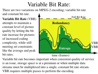
Simulation Results • Measurement of the SNR in subchannel k • S = 1000 symbols • Every subchannel in a symbol loaded with a random 2-bit constellation point Xki, passed through the channel, TEQ block and FEQ block (where applicable) to obtain Yki • Bit rate reported is then
Effect of TEQ Size on Bit Rate Data rates achieved for different number of TEQ taps, MN = 512, n= 32, input power = 23.93 dBm, AWGN power = -140 dBm/Hz, and NEXT modeled as 49 disturbers. Accuracy of bit rate: 60 kbps. (a) CSA loop 2 (b) CSA loop 7
Effect of Transmission Delay on Bit Rate Data rates achieved as a function of D for CSA loop 1.N = 512, n= 32, input power = 23.93 dBm, AWGN power = -140 dBm/Hz, and NEXT modeled as 49 disturbers. Accuracy of bit rate: 60 kbps.
Simulation Results • We evaluate TEQFB, proposed single TEQ, MBR, Min-ISI, LS PTE, MMSE-UTC and MMSE-UEC for CSA loops 1-8 • Results presented in a table • Each row entry • Final row entry
TEQ Design Methods - Comparison CSA – carrier serving area, MBR – Maximum Bit Rate, Min-ISI – Minimum InterSymbol Interference TEQ Design, LS PTE – Least-squares Per-Tone Equalizer, MMSE – Minimum Mean Square Error, UTC – Unit Tap Constraint, UEC – Unit Energy Constraint
TEQFB Data Rates Highest data rates in Mbps achieved by TEQFB for TEQ lengths 2-32, input power = 23.93 dBm
Backup Slides Milos Milosevic Lucio F. C. Pessoa Brian L. Evans Ross Baldick
CSA Loops Configuration of eight standard carrier serving loops (CSA). Numbers represent length in feet/ gauge. Vertical lines represent bridge taps. From Guner, Evans and Kiaei, “Equalization For DMT To Maximize bit Rate”.
Selected Previous TEQ Design Methods • Minimize mean squared error • Minimize mean squared error (MMSE) method[Chow & Cioffi, 1992] • Geometric SNR method[Al-Dhahir & Cioffi, 1996] • Minimize energy outside of shortened channel response • Maximum Shortening SNR method[Melsa, Younce & Rohrs, 1996] • Divide-and-Conquer methods – Equalization achieved via a cascade of two tap filters[Lu, Evans & Clark, 2000] • Minimum ISI method - Near-maximum bit rate at TEQ output[Arslan, Evans & Kiaei, 2001] • Maximum Bit Rate (MBR) - Maximize bit rate at TEQ output [Arslan, Evans & Kiaei, 2001] • Per-tone equalization • Frequency domain per-tone equalizer [Acker, Leus, Moonen, van der Wiel & Pollet, 2001]
Goertzel Filters • Used to calculate single DFT point • Denote with yk(n) as the signal emanating from TEQ making up TEQFB • Then, the corresponding single point DFT Yk is: where Gk (-1) = Gk (-2) = 0 and n={0,1,…,N}