Download
1 / 34
340 likes | 531 Views
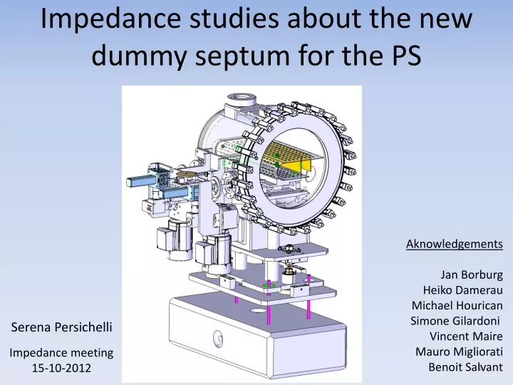
Impedance studies about the new dummy septum for the PS. Aknowledgements Jan Borburg Heiko Damerau Michael Hourican Simone Gilardoni Vincent Maire Mauro Migliorati Benoit Salvant. Serena Persichelli. Impedance meeting 15-10-2012. Aim of the study.

E N D
Impedance studies about the new dummy septum for the PS Aknowledgements Jan Borburg Heiko Damerau Michael Hourican Simone Gilardoni Vincent Maire Mauro Migliorati Benoit Salvant Serena Persichelli Impedance meeting 15-10-2012
Aim of the study • Establish the impact of the dummy septum on the total impedance of the PS (longitudinal and transverse) and the effects on the stability of the beam • Verify the presence of parasitic and trapped modes that can be excited by the beam in the septum, evaluating frequencies and configurations with Eigenmode simulations (CST MWS and HFSS) and Wakefield simulations (CST PS) • Consider the possibility to make some changes in the geometry (RF screen in particular) evaluating the effects on the impedance • Consider the possibility of using ferrites in order to damp impedance sources (parasitic and trapped modes)
Agenda • Dummy Septum proposal • Tank design • Blade design • Impedance of the septum with only the copper blade • Wakefield CST PS analysis • EigenmodeCST MWS analysis • Impedance of the septum with a copper blade and a steel screen • Wakefield CST PS analysis • Impedance of the septum with the displacement system • Wakefield CST PS analysis • Evaluation of the impedance with/without screen • Wakefield CST PS analysis • Eigenmode CST MWS analysis • Contribution to PS impedance budget • Longitudinal impedance at low frequency with/without screen • Transverse impedance at low frequency with/without screen • Conclusions and perspectives
Agenda • Dummy Septum proposal • Tank design • Blade design • Impedance of the septum with only the copper blade • Wakefield CST PS analysis • EigenmodeCST MWS analysis • Impedance of the septum with a copper blade and a steel screen • Wakefield CST PS analysis • Impedance of the septum with the displacement system • Wakefield CST PS analysis • Evaluation of the impedance with/without screen • Wakefield CST PS analysis • Eigenmode CST MWS analysis • Contribution to PS impedance budget • Longitudinal impedance at low frequency with/without screen • Transverse impedance at low frequency with/without screen • Conclusions and perspectives
A dummy septum to mitigate radiation for the PS MT extraction Displacement system SECTION 15 RF screen Copper Base (heat sink) Internal bellows Courtesy of Mike Hourican The dummy septum, located in section 15, should absorb the particles during the rise time of the MT extraction kickers, providing the required reduction in activation in the extraction area. The impacts on the thick blade of the magnetic extraction, located in section 16, will be reduced thanks to a 40 cm long, 7 cm high and 4.2 mm thick copper blade inside the beam tube.
Dummy septum tank design 30 mm Internal radius of the tank: 17.3 cm Length of the tank: 45.9 cm Cut-off frequency of circular pipe of length 46 cm and radius 17.3cm fcTE111 = 0.6 GHz PS elliptical pipe characteristics: a/2=7.3 cm b/2=3.5 cm fcTM010 = 2.75 GHz
Dummy septum internal design: blade There are two positions available for the blade, thanks to presence of the displacement system Parking potition Operational position • What should we expect from such geometry? • The presence of the blade modifies the arrangement of the mode of the pillbox cavity (high order modes) • Parasitic modes of the blade • Degeneration of the intrinsic modes of the cavity • Trapped modes • Dummy septum blade characteristics: • Material: copper • Length: 40 cm • High: 7 cm • Thickness: 4.2 mm
Agenda • Dummy Septum proposal • Tank design • Blade design • Impedance of the septum with only the copper blade • Wakefield CST PS analysis • EigenmodeCST MWS analysis • Impedance of the septum with a copper blade and a steel screen • Wakefield CST PS analysis • Impedance of the septum with the displacement system • Wakefield CST PS analysis • Evaluation of the impedance with/without screen • Wakefield CST PS analysis • Eigenmode CST MWS analysis • Contribution to PS impedance budget • Longitudinal impedance at low frequency with/without screen • Transverse impedance at low frequency with/without screen • Conclusions and perspectives
Dummy septum with copper blade: CST PS simulations 0.57 GHz Resonating modes can be excited by a short bunch passing close to the blade 0.29 GHz • The blade introduces parasitic modes at frequencies lower that the cut-off of the pillbox cavity • The first two resonating modes in the structure are due only to the presence of the blade
Dummy septum with copper blade: CST MW Eigenmode simulations *Kloss=V2/4U U=1 Joule (CST)
Agenda • Dummy Septum proposal • Tank design • Blade design • Impedance of the septum with only the copper blade • Wakefield CST PS analysis • EigenmodeCST MWS analysis • Impedance of the septum with a copper blade and a steel screen • Wakefield CST PS analysis • Impedance of the septum with the displacement system • Wakefield CST PS analysis • Evaluation of the impedance with/without screen • Wakefield CST PS analysis • Eigenmode CST MWS analysis • Contribution to PS impedance budget • Longitudinal impedance at low frequency with/without screen • Transverse impedance at low frequency with/without screen • Conclusions and perspectives
Dummy septum internal design:blade and screen • Materials: • Blade: copper • Screen and tank: stainless steel • Design considered for CST simulations: • The holes of the screen have been eliminated (frequencies don’t vary) • Without holes we expect very small effect compared to the frequencies of the PS (other investigation could be done, with tetrahedral mesh for instance) • Elliptical pipe have been extended to avoid negative impedance effects Length of the screen/tank: 48.9 cm
σ=26 cm fMAX=0.7 GHz Wakelength=30 m Method: Direct CST PS wakefield simulations Longitudinal impedance Transverse impedance --Re --Im 0.28 GHz --Re --Im
Longitudinal electric field:a parasitic mode of the blade at 0.28 GHz TEM mode with fringe field
Agenda • Dummy Septum proposal • Tank design • Blade design • Impedance of the septum with only the copper blade • Wakefield CST PS analysis • EigenmodeCST MWS analysis • Impedance of the septum with a copper blade and a steel screen • Wakefield CST PS analysis • Impedance of the septum with the displacement system • Wakefield CST PS analysis • Evaluation of the impedance with/without screen • Wakefield CST PS analysis • Eigenmode CST MWS analysis • Contribution to PS impedance budget • Longitudinal impedance at low frequency with/without screen • Transverse impedance at low frequency with/without screen • Conclusions and perspectives
Dummy septum internal designwith the displacement system • The design considered for CST simulations has been simplify from the original mechanical model! • For simulations the holes of the screen have been eliminated • Elliptical pipe have to be extended to avoid negative impedance effects
CST PS wakefield simulations: longitudinal impedance Longitudinal impedance σ=10 cm fMAX=1.8 GHz Wakelength=50 m Method: Direct Modes excited by bunch of 10 cm length circulating in the centre of the septum 0.38 GHz 0.22 GHz 0.38 GHz 0.47 GHz 0.26 GHz 0.50 GHz 0.38 GHz 0.37 GHz
CST PS wakefield simulations: transverse impedance Transverse impedance --Re --Im --Re --Im 0.22 GHz σ=10 cm fMAX=1.8 GHz Wakelength=50 m Method: Direct --Re --Im 0.22 GHz
Agenda • Dummy Septum proposal • Tank design • Blade design • Impedance of the septum with only the copper blade • Wakefield CST PS analysis • EigenmodeCST MWS analysis • Impedance of the septum with a copper blade and a steel screen • Wakefield CST PS analysis • Impedance of the septum with the displacement system • Wakefield CST PS analysis • Evaluation of the impedance with/without screen • Wakefield CST PS analysis • Eigenmode CST MWS analysis • Contribution to PS impedance budget • Longitudinal impedance at low frequency with/without screen • Transverse impedance at low frequency with/without screen • Conclusions and perspectives
Comparison of the impedance with/without screen σ=10 cm fMAX=1.8 GHz Wakelength=50 m Method: Direct Without the screen 0.24 GHz With the screen 0.22 GHz
Comparison of wake potential with/without screen Longitudinal wake potential ---Pulse ---Without the screen ---With the screen The residual oscillations are due to the 0.24 GHz mode that has components over all the axis
Eigenmodes (CST MWS): without screen *Kloss=V2/4U U=1 Joule (CST)
Eigenmodes (CST MWS): with screen *Kloss=V2/4U U=1 Joule (CST)
Agenda • Dummy Septum proposal • Tank design • Blade design • Impedance of the septum with only the copper blade • Wakefield CST PS analysis • EigenmodeCST MWS analysis • Impedance of the septum with a copper blade and a steel screen • Wakefield CST PS analysis • Impedance of the septum with the displacement system • Wakefield CST PS analysis • Evaluation of the impedance with/without screen • Wakefield CST PS analysis • Eigenmode CST MWS analysis • Contribution to PS impedance budget • Longitudinal impedance at low frequency with/without screen • Transverse impedance at low frequency with/without screen • Conclusions and perspectives
Contribution to PS impedance budget: dummy septum with screen Longitudinal impedance A bunch of 1.2 m length circulating in the center of the septum excite a longitudinal impedance that is inductive with a small resistive part At very low frequencies the contribution of the dummy septum (with the screen) to the longitudinal impedance of the PS is predicted to be negligible M. Migliorati et al., Evaluation of the broadband longitudinal impedance of the CERN PS, CERN-ATS-Note-2012-064 MD. - 2012.
Contribution to PS impedance budget: dummy septum without the screen Longitudinal impedance A bunch of 90 cm length circulating in the center of the septum excite a purely inductive longitudinal impedance At low frequencies the contribution of the dummy septum (without the screen) to the total longitudinal impedance of the PS is about the 0.7% M. Migliorati et al., Evaluation of the broadband longitudinal impedance of the CERN PS, CERN-ATS-Note-2012-064 MD. - 2012.
Transverse dipolar impedance (screen) A bunch of 90 cm length displaced in the transverse planes from the centre excites a transverse impedance that is constant at low frequencies: Estimated total effective transverse impedance in the PS: At low frequencies the contribution of the septum (with the screen) to the PS total transverse effective impedance is predicted to be negligible
Transverse dipolar impedance (no screen) A bunch of 90 cm length displaced in the transverse planes from the centre excites a transverse impedance that is constant at low frequencies: Estimated total effective transverse impedance in the PS: At low frequencies the contribution of the septum (without the screen) to the PS total transverse effective impedance is predicted to be negligible
Agenda • Dummy Septum proposal • Tank design • Blade design • Impedance of the septum with only the copper blade • Wakefield CST PS analysis • EigenmodeCST MWS analysis • Impedance of the septum with a copper blade and a steel screen • Wakefield CST PS analysis • Impedance of the septum with the displacement system • Wakefield CST PS analysis • Evaluation of the impedance with/without screen • Wakefield CST PS analysis • Eigenmode CST MWS analysis • Contribution to PS impedance budget • Longitudinal impedance at low frequency with/without screen • Transverse impedance at low frequency with/without screen • Conclusions and perspectives
Conclusions • Wakefield simulations on CST PS show that resonances could be excited by a short bunch (10-26 cm) passing in the center or close to the blade. Results obtained with CST MWS and HFSS agree well for the estimation of the frequencies and the modal configuration in the structure. • Continuity between the RF screen and the tank has to be assured in order to avoid the generation of parasitic modes at low frequencies. • The presence of the screen is important in order to avoid many parasitic modes with an high loss factor. • At low frequencies the contribution of the dummy septum to the total impedance of the PS is predicted to be negligible.
Perspectives Example: PS 200 MHz cavity (damped with 3 PIN diodes lines): Q=130 R/Q= 28.5 Ω Rs=3.7 kΩWell above the residual shunt impedance of 249 Ω estimated for the dummy septum at 220 MHz! Is it necessary to damp the mode at 220 MHz? Possible problems: • Coupled bunch instability (longitudinal) (220 MHz is probably too high for the PS to create instabilities before bunch rotation?) Posible technicalsolutions in case of instabilities: • Using ferrite • Using dampingresistors • Connecting the blade to an externalload • Inserting a loop coupled with the magnetic field of the modes
PS Bunch Spectrum @ Flat bottom (1ms after injection): after 200 MHz we expect no power! 80 MHz 0