Download

1 / 40
790 likes | 1.79k Views
Today Imaging with coherent light. • Coherent image formation –space domain description: impulse response –spatial frequency domain description: coherent transfer function. The 4F system. Fourier transform relationship. Fourier transform relationship. The 4F system. Theorem:.

E N D
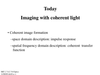
Today Imaging with coherent light • Coherent image formation –space domain description: impulse response –spatial frequency domain description: coherent transfer function MIT 2.71/2.710 Optics 11/08/04 wk10-a-
The 4F system Fourier transform relationship Fourier transform relationship MIT 2.71/2.710 Optics 11/08/04 wk10-a-
The 4F system Theorem: MIT 2.71/2.710 Optics 11/08/04 wk10-a-
The 4F system object plane Fourier plane Image plane MIT 2.71/2.710 Optics 11/08/04 wk10-a-
The 4F system object plane Fourier plane Image plane MIT 2.71/2.710 Optics 11/08/04 wk10-a-
The 4F system with FP aperture object plane Fourier plane : aperture-limited Image plane: blurred i. e. low-pass filtered MIT 2.71/2.710 Optics 11/08/04 wk10-a-
Impulse response & transfer function A point source at the input plane ... ... results not in a point image but in a diffraction pattern h(x’,y’) Point source at the origin ↔delta function δ(x,y) h(x’,y’) is the inpulse response of the system More commonly, h(x’,y’) is called the Coherent Point Spread Function (Coherent PSF) MIT 2.71/2.710 Optics 11/08/04 wk10-a-
Coherent imaging as a linear, shift-invariant system Thin transparency output amplitude impulse response illumi nation convolution Fourier transform Fourier transform transfer function (≡plane wave spectrum multiplication transfer function H(u,v): akapupil function MIT 2.71/2.710 Optics 11/08/04 wk10-a-
Transfer function & impulse response of rectangular aperture Impulse response: Airy function Transfer function: circular aperture MIT 2.71/2.710 Optics 11/08/04 wk10-a-
Coherent imaging as a linear, shift-invariant system Example: 4F system with circular aperture @ Fourier plane Thin transparency output amplitude Impulse response convolution illumi nation Fourier transform Fourier transform transfer function (≡plane wave spectrum multiplication MIT 2.71/2.710 Optics 11/08/04 wk10-a-
Transfer function & impulse response of rectangular aperture MIT 2.71/2.710 Optics 11/08/04 wk10-a-
Coherent imaging as a linear, shift-invariant system Example: 4F system with circular aperture @ Fourier plane Thin transparency output amplitude Impulse response convolution illumi nation Fourier transform Fourier transform transfer function (≡plane wave spectrum multiplication MIT 2.71/2.710 Optics 11/08/04 wk10-a-
Aperture–limited spatial filtering Image plane: grating is imaged with lateral de-magnification object plane: grating generates one spatial frequency Fourier plane: aperture unlimited (all orders pass) MIT 2.71/2.710 Optics 11/08/04 wk10-a-
Aperture–limited spatial filtering Image plane: grating is not imaged only 0th order (DC component) surviving object plane: grating generates one spatial frequency Fourier plane: aperture limited (some orders cut off) MIT 2.71/2.710 Optics 11/08/04 wk10-a-
Spatial frequency clipping field after input transparency field before filter field after filter field at output (image plane) MIT 2.71/2.710 Optics 11/08/04 wk10-a-
Effect of spatial filtering Fourier plane filter with circ-aperture Original object (sinusoidal spatial variation, i.e. grating) Frequency-filtered image (spatial variation blurred out, only average survives) MIT 2.71/2.710 Optics 11/08/04 wk10-a-
f1=20cm λ=0.5μm Spatial frequency clipping monochromatic coherent on-axis illumination Fourier plane cire-aperture object plane Transparency Fourier filter transitivity intensity at input plane Intensity before Fourier Filter (negative contrast) MIT 2.71/2.710 Optics 11/08/04 wk10-a-
Space-Fourier coordinate transformations :pixel size :frequency resolution spare domain Spatial Frequency domain Nyquist relationships. MIT 2.71/2.710 Optics 11/08/04 wk10-a-
4F coordinate transformations :pixel size spare domain Fourier plane Nyquist relationships. MIT 2.71/2.710 Optics 11/08/04 wk10-a-
Spatial frequency clipping f1=20cm λ=0.5μm monochromatic coherent on-axis illumination Fourier plane cire-aperture Image plane observed field object plane transparency Fourier filter transitivity intensity at input plane Intensity before Fourier Filter (negative contrast) MIT 2.71/2.710 Optics 11/08/04 wk10-a-
Formation of the impulse response Image plane: Fourier transform of aperture, Airy pattern object plane: pinhole generates spherical wave Fourier plane: circ-aperture limited (plane wave is clipped) MIT 2.71/2.710 Optics 11/08/04 wk10-a-
Low–pass filtering field after input transparency field before filter field after filter field at output (image plane) (Airy pattern) MIT 2.71/2.710 Optics 11/08/04 wk10-a-
Effect of spatial filtering Fourier plane filter with circ-aperture Original object (small pinhole ⇔impulse, generating spherical wave past the transparency) Impulse reponse (aka point point-spread function, original point has blurred to an Airy pattern, or jinc) MIT 2.71/2.710 Optics 11/08/04 wk10-a-
f1=20cm λ=0.5μm Low–pass filtering the impulse monochromatic coherent on-axis illumination object plane transparency Fourier plane cire-aperture intensity at input plane Fourier filter transitivity Intensity before Fourier Filter (negative contrast) MIT 2.71/2.710 Optics 11/08/04 wk10-a-
Spatial frequency clipping monochromatic coherent on-axis illumination Fourier plane cire-aperture Image plane observed field object plane transparency intensity at input plane Intensity after Fourier filter Intensity at output plane note: pseudo-accentuated sidelobes MIT 2.71/2.710 Optics 11/08/04 wk10-a-
Low-pass filtering with the 4F system monochromatic coherent on-axis illumination Fourier plane cire-aperture Image plane observed field object plane transparency field arriving At Fourier plane Fourier transform field arriving from Fourier plane MIT 2.71/2.710 Optics 11/08/04 wk10-a-
Spatial filtering with the 4F system monochromatic coherent on-axis illumination Fourier plane cire-aperture Image plane observed field object plane transparency field arriving At Fourier plane Fourier transform Fourier transform field arriving from Fourier plane MIT 2.71/2.710 Optics 11/08/04 wk10-a-
Examples: the amplitude MIT pattern Original MIT pattern MIT 2.71/2.710 Optics 11/08/04 wk10-a-
Weak low–pass filtering Pinhole, radius 2.5mm Filtered with pinhole, radius 2.5mm Fourier filter Intensity @ image plane f1=20cm λ=0.5μm MIT 2.71/2.710 Optics 11/08/04 wk10-a-
Moderate low–pass filtering (aka blurringblurring) Pinhole, radius 1mm Filtered with pinhole, radius 1mm Fourier filter Intensity @ image plane f1=20cm λ=0.5μm MIT 2.71/2.710 Optics 11/08/04 wk10-a-
Strong low–pass filtering Pinhole, radius 0.5mm Filtered with pinhole, radius 0.5mm Fourier filter Intensity @ image plane f1=20cm λ=0.5μm MIT 2.71/2.710 Optics 11/08/04 wk10-a-
Moderate high–pass filtering Reflective disk, radius 0.5mm Filtered with reflective disk, radius 0.5mm Fourier filter Intensity @ image plane f1=20cm λ=0.5μm MIT 2.71/2.710 Optics 11/08/04 wk10-a-
Strong high–pass filtering (aka edge enhancement) Reflective disk, radius 2.5mm Filtered with reflective disk, radius 2.5mm Fourier filter Intensity @ image plane f1=20cm λ=0.5μm MIT 2.71/2.710 Optics 11/08/04 wk10-a-
1-dimensional blurring Filtered with horizontal slit, width 2mm Horizontal slit, width 2mm Fourier filter Intensity @ image plane f1=20cm λ=0.5μm MIT 2.71/2.710 Optics 11/08/04 wk10-a-
1-dimensional blurring Filtered with vertical slit, width 2mm vertical slit, width 2mm Fourier filter Intensity @ image plane f1=20cm λ=0.5μm MIT 2.71/2.710 Optics 11/08/04 wk10-a-
Phase objects thickness protruding part phase-shifts coherent illumination by amount φ=2π(n-1)t/λ glass plate (transparent) Often useful in imaging biological objects (cells, etc.) MIT 2.71/2.710 Optics 11/08/04 wk10-a-
Viewing phase objects Original 0.1 rad phase MIT pattern (phase) Original phase MIT pattern (intensity) Amplitude (need interferometer) Intensity (object is invisible) MIT 2.71/2.710 Optics 11/08/04 wk10-a-
Zernicke phase-shift mask phase-shift mask (phase), radii 5mm & 1mm (phase) phase-shift mask (magnitude), radii 5mm & 1mm MIT 2.71/2.710 Optics 11/08/04 wk10-a-
Imaging with Zernicke mask phase-shift mask (phase), radii 5mm & 1mm (phase) Filtered with, phase-shift mask, radii 5mm & 1mm Fourier filter Intensity @ image plane f1=20cm λ=0.5μm MIT 2.71/2.710 Optics 11/08/04 wk10-a-
Imaging with Zernicke mask phase-shift mask (phase), radii 5mm & 0.1mm (phase) Filtered with, phase-shift mask, radii 5mm & 0.1mm Fourier filter Intensity @ image plane f1=20cm λ=0.5μm MIT 2.71/2.710 Optics 11/08/04 wk10-a-