CSC 311 Chapter Nine
300 likes | 463 Views
Token Ring Lans: IEEE Standard 802.5. CSC 311 Chapter Nine. Like Ethernet, the token ring is a MAC protocol sitting between the logical link control and the physical layer. Data rates are listed at 4 Mbps and 1 Mbps but IBM token rings can run at 4, 16, or 100Mbps.

CSC 311 Chapter Nine
E N D
Presentation Transcript
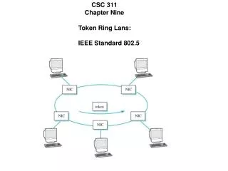
Token Ring Lans: IEEE Standard 802.5 CSC 311Chapter Nine
Like Ethernet, the token ring is a MAC protocol sitting between the logical link control and the physical layer. Data rates are listed at 4 Mbps and 1 Mbps but IBM token rings can run at 4, 16, or 100Mbps. Differential Manchester Encoding is used. Devices are configured in a ring. Any particular device can send only to its neighbors, in most cases only one neighbor as data flow is usually unidirectional. Unlike Ethernet, collisions do not occur in token ring networks, contention is controlled by use of a special packet called a token. Only one token circulates the ring, and a device wishing to send must have possession of the token in order to send. CSC 311Chapter Nine
In some token ring configurations, the failure of a single device can cause failure of the entire network. Each device, in turns checks the destination address of a data frame, If the address matches the device address, the frame is copied, a few bits changed and the frame is passed to the next station. If the address does not match, the frame is simply passed to the next station. CSC 311Chapter Nine
The token is a special frame. Both token and frame formats are shown below: CSC 311Chapter Nine
Each frame has a starting delimiter SD and an ending delimiter ED. The SD has a special signal pattern: JK0JK000 How to you send a J or K? By violating differential Manchester signal rules; CSC 311Chapter Nine
Sending a J or K We simply violate differential Manchester encoding rules; remember, both Manchester and differential Manchester encoding require a signal transition in the middle of the bit period: To send J: start out like you are sending a 0, ie, transition at the beginning of the bit period, but do not transition in the middle of the bit period. To send K: start out like you are sending a 1, ie, no transition at the beginning of the bit period, but do not transition in the middle. The signals, J and K, will not appear naturally in data, so there is no confusion. CSC 311Chapter Nine 1 0 J 1 K 1
Notice that the ending delimiter sequence is: JK1JK11E, the “E” bit is an error bit. Remember that the frame check sequence using CRC uses modulo 2 arithmetic to check for errors, since this is just the EXOR of the received bits and the divisor bits, AND, since the error check operation can begin as soon as a string of bits equal in length to the divisor function has been received and the next step in the operation is performed as soon as the next single bit arrives, by the time the last bit arrives, the error check is complete and it is a simple matter to set the E bit, error bit, to indicate whether or not an error has occurred. The frame status field, FS has two bits which can be set by the receiving station: address recognized bit and frame copied bit. CSC 311Chapter Nine
Access Control Field AC p p p t m r r r the p bits refer to priority the t bit t = 0 this is a token frame t = 1 this is a data frame m monitor bit r bits are used for reservations All of these functions are necessary to efficient operation of a token ring LAN CSC 311Chapter Nine
Reservations: Tokens can only be claimed in a round robin fashion by stations unless We implement a reservation system. We prioritize devices on the ring, and assign a priority to the token This permits devices to capture the token in a different order. A device can only claim the token if it has a sufficient priority. Who defines the token’s priority. Initially a device sends a token with priority 0. CSC 311Chapter Nine
Example: A token arrives with a priority higher than the device’s priority. The device Cannot claim the token but it may be able to make a reservation. It would examine the reservation bits, if the current reservation is lower Than that devices priority, it replaces the reservation with its priority. If the current reservation is higher than the priority of that device, it cannot Make a reservation at that time. When a device drains a frame from the ring, it creates a new token. It examines the reservation bits and creates a new token with that Priority. It then stores the old priority and the new one (current) on its stack locally, It becomes “a stacking station” and only it can restore the token to its Original priority. When the new token begins to travel the ring, it is claimed by the first Station with an equal or higher priority. CSC 311Chapter Nine
The device that originated a frame is the one which must Remove it and put a new token on the ring. What priority should The new token have? Two possibilities: One: Some device with a higher priority than the frames’s priority Has made a reservation. The device would give the new token a Priority equal to the reservation value and make new reservation value = 0 to give stations a chance to make a new reservation. Any device with raises the token priority has the responsibility to lower It, this is why the station (stacking station) stores the old and current Priority. CSC 311Chapter Nine
Second case: reservation on incoming frame was lower than priority of incoming frame Priority. New token’s priority must be lowered, but by whom? If the current device Did not raise the priority, it cannot lower it. Presumably the token would Eventually reach the stacking station and thus be lowered. If the current station is the stacking station, it creates a new token with A lower priority, but what priority? The stacking station compares the incoming reservation value with its Old stacked priority and chooses the greater value CSC 311Chapter Nine
Wireless Networks IEEE Standard 802.11 CSC 311Chapter Nine
The previous examples represent LANs in which the devices are Actually physically connected. It is often desirable to implement LANs That are not physically connected. These are Wireless LANs WLAN Usually, you will want to have contact with a traditional wired LAN, this Is accomplished through an “access point” CSC 311Chapter Nine
Wireless LANs use either of two modes of communication: Infrared waves Radio waves Infrared devices use light emitting diodes or laser diodes The beams can be aimed directly at the receiver (point to point) Or they can be reflected off the ceiling or walls, the latter method is Easier. One advantage of IR systems is that, since the signals do not penetrate Walls, infrared signals are not regulated by the FCC. For this reason, the same IR frequencies can be used in different areas Of a building without interference IR signals are not affected by radio interference, though bright sunlight Or heat sources can be a problem. CSC 311Chapter Nine
Systems that use radio waves usually have built-in transmitters And receivers. Broadcasting on a single frequency can cause problems from Interference with competing devices or simple electromagnetic Noise, motors, etc. Using a single frequency makes the signals easier to jam and makes it easier for some third party to intercept the signals. To overcome these problems, standard 802.11 uses “spread spectrum”. This technology is also used in cordless and cellular Telephones. Instead of using a narrow frequency band, spread spectrum transmission spreads the signal over a wider range of frequencies a wider bandwidth. CSC 311Chapter Nine
This improves the noise immunity, since noise is usually confined to a small range of frequencies. It is more secure, since the data is spread among a number of frequencies, an eavesdropper on one frequency would hear only a small part of the message which might appear to be noise. How is this accomplished? FREQUENCY HOPPING SPREAD SPECTRUM FHSS Using a pseudo random number generator, we “hop” among a selected range of frequencies, sending only a few bits on each frequency. This may be as little as one signal element or even a part of one signal element (fast FHSS) Both the sender and receiver use the same pseudo-random number generator algorithm and the same seed value. To an outsider, the sequence would appear to be completely random, but if both parties use the same algorithm and the same seed value, the sequence is deterministic. CSC 311Chapter Nine
FHSS AND FAST FHSS SLOW CSC 311Chapter Nine FAST
DIRECT SEQUENCE SPREAD SPECTRUM DSSS works in a different way. FHSS uses, over time, a wide frequency band but at any given instant is transmitting over a very narrow band. DSSS expands a single data bit into many bits. This increases the required data rate and forces the transmitter to operate at a higher bit rate which, in turn, requires a higher bandwidth. DSSS uses a “chipping sequence” of length N. The chipping sequence is determined, just as in FHSS, by a pseudo- random sequence generator, again with both sender and receiver using the same generator algorithm and the same seed value, so that the sequence of values generated is deterministic. Each data bit is combined, EXOR, with the chipping sequence to produce a “chipping code” of length N for each data bit. CSC 311Chapter Nine
If you use a chipping code of length N, then each data bit would require transmission of ten code bits, obviously greatly increasing the number of bits that must be transmitted. Anyone intercepting this transmission would not be able to determine what is being transmitted unless they have the chipping sequence. CSC 311Chapter Nine
On the receiving end, use the exact same chipping sequence and decryption procedure CSC 311Chapter Nine receiver chipping sequence 0 0 1 0 1 1 0 1 1 0 0 0 1 1 0 1 receiver data stream 0 0 0 0 1 1 1 1 0 0 0 0 1 1 1 1 actual data 0 1 0 1
We saw that with Ethernet and Token Ring wired LANs, we needed some method to allocate access to the medium, to determine who gets to transmit. We have the same problem with wireless LANs. How do we handle contention for access to the network? A contention protocol such as the CSMA/CD used by Ethernet will not work for a wireless LAN, you can not assume that you can listen to the medium to sense when another device is transmitting or to hear collisions that might occur. CSC 311Chapter Nine
Hidden Station Problem Scenario One: Assume stations A and B are infrared devices, the wall prevents either device from sensing the other’s signal, so both could transmit to the receiver simultaneously with realizing it and causing a collision CSC 311Chapter Nine Scenario Two: All stations are switched to radio waves, so the wall is no longer a problem. However, let us assume, as indicated, that stations A and C are on opposite sides of the access point receiver, both A and C are within range of the receiver, but not within range of each other, both could transmit to the receiver without being able to hear each other, so ordinary CSMA/CD would not work in either case.
How do we manage contention on Wireless LANs? • IEEE Standard 802.11 includes a MAC layer protocol called • DISTRIBUTED COORDINATION FUNCTION DCF • this implements “Carrier Sense Multiple Access with Collision Avoidance” • CSMA/CA • Just like CSMA/CD it does not eliminate all collisions, but it does reduce them. • THE CSMA/CA PROTOCOL: • Source wants to send. It first senses the medium, if busy, it waits until clear • using a persistence strategy as described for CSMA/CD. If clear, sender • waits an additional amount of time. The extra time is used to prioritize • activities. Additional wait times are defined by a short interframe • space (SIFS) and a DCF interframe space (DIFS) that is longer than SIFS. • When a device is contending for the medium frame, it waits for a DIFS. • After the DIFS wait, if medium is still clear, it sends a Request to Send • (RTS) frame to destination, this frame also contains a duration value CSC 311Chapter Nine
The destination point receives the RTSD frame and must • respond by sending a Clear to Send (CTS) frame • back to source. However, it must also contend for • the medium since other sources may wish to send. • These other sources may not have heard the RTS, the • destination proceeds as in the previous case, except • when the medium is clear, it only waits a DIFS which is • shorter than SIFS. The effectively gives the destination • higher priority than other sources wishing to initiate a • transmission with an RTS since they must wait an SIFS. • When the source receives the CTS frame, it has permission to send • data. If two RTS frames collide, the sender will not know, but • the destinations will, so no destination will send a CTS, the • senders, recognizing that they received not CTS in a specified • amount of time, will assume a collision has occurred, both • will wait a random amount of time and try again. • Other devices will receive the CTS frame along with the duration • of the impending transmission and will wait the necessary time • period before attempting to send. Effectively giving the device • whose RTS evoked the CTS, exclusive access to the medium. CSC 311Chapter Nine
Once the source has received the CTS frame, it sends a data frame • collisions should not occur because other devices know • not to send. • When the destination receives the data frame, it returns an ACK, so • the source knows the data has been received. • This is a simplified discussion of CSMA/CD. There is another feature • called Point Coordination Function (PCF) used on systems requiring • some measure of coordination and control. The available • transmission time is divided into “frames” much like slotted Aloha. • We will not discuss further here. CSC 311Chapter Nine
ADDRESSING: The 802.11 frame format specifies four address fields for each frame, why? CSC 311Chapter Nine Wireless LAN Infrastructure
A set of wireless devices with which a single AP communicates • defines a basic service set (BSS) • There may be multiple APs and there may also be a distribution • system (DS) to which the BSSs are connected. • The DS may be a LAN or a collection of LANs, but in all cases it allows • a device in one BSS to communicate with a device in another BSS or to • access printers, servers, etc. • So when a device sends a frame, there are four possibilities: • Case Description Address1 Address 2 Address3 Address4 • (receiver) (Transmitter) • X sends frame to Z, frame stays Z X BSS1 ------ • within BSS1 • X send frame to Y, Frame first AP1 X Y ------- • goes to AP1 • 3. API send frame originating at AP2 AP1 Y X • X to AP2 over a wireless DS • Frame is destined for Y • 4. AP2 send frame originating at X to Y Y AP2 X ---- CSC 311Chapter Nine
All four cases have two things in common: Address1 always specifies the device that should receive the frame. Address 2 always specifies the device that transmitted the frame CSC 311Chapter Nine
Security: In wireless networks, security is obviously a problem. 802.11 standard includes a security protocol called: Wired Equivalent Privacy (WEP) The encryption algorithm uses a 40 bit secret key and appends a 24 bit initialization vector to create a 64 bit key, newer equipment uses 128 bits There are several variations of 802.11, Wi-Fi (802.11b) uses radio frequency waves in the 2.4 GHz range and is rated at 11 Mbps, compared to 1 or 2 Mbps for 802.11. Uses on DSSS since the higher rate could not be achieved using FHSS CSC 311Chapter Nine