Download
1 / 13
130 likes | 264 Views
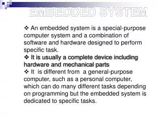
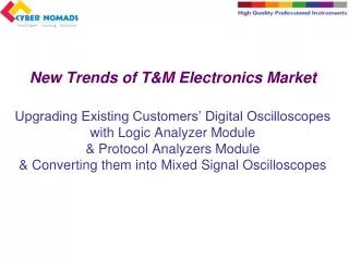
The electronics market is shifting towards enhanced development tools, prompting the upgrade of existing digital oscilloscopes with logic analyzer and protocol analyzer modules. This transformation enables mixed signal oscilloscopes, facilitating the analysis of both analog and digital signals. Our comprehensive solutions include PC-based logic analyzers with frequencies from 100Hz to 1GHz, supporting various protocols like I2C, SPI, and USB. By connecting these modules to traditional instruments, customers can significantly enhance their capabilities in measuring and debugging modern electronic systems.

E N D
New Trends of T&M Electronics MarketUpgrading Existing Customers’ Digital Oscilloscopes with Logic Analyzer Module & Protocol Analyzers Module& Converting them into Mixed Signal Oscilloscopes
Development of Embedded System http://www.tcs.com/sitecollectiondocuments/white%20papers/tcs_hitech_whitepaper_Trends-Implications-Embedded-Systems-Development.pdf
Existing Facilities In Customers’ Lab Traditional Instrument such as DSO, Generator, Development Kits, Counter etc without Logic Analyzer and Digital Protocol Decoders cannot be satisfied in Development of New Electronics Systems.
We Offer PC Based Logic Analyzers with many types of models 100Hz~1GHz frequencies Channels: 16 / 32/ 64 Memory: 32Kbits/ 64Kbits/ 128Kbits/2Mbits More then 80 types protocol analyzers such as I2C/ SPI/ UART/ CAN/ MOD/ LIN/ IRDA/ SD/ USB1.1… Our LA software is able to catch and analysis signals of Oscilloscopes by using NI-VISA
Upgrading Oscilloscope with Logic Analyzer Module & Protocol Analyzer Module • Step 3: Connecting Oscilloscope to PC via USB cable • Step 4: Connecting Logic Analyzer to PC via USB cable • Step 5: Connect trigger out of LA to trigger in of oscilloscope • Step 6: Connect ground between LA and oscilloscope Logic Analyzer
Step 7: Run Logic Analyzer Software Step 8: Select Tools and Click DSO to select channels Step 9: DSO-stacked Setting, click connect, click OK. Upgrading Oscilloscope with Logic Analyzer Module & Protocol Analyzer Module
Example: Upgrading oscilloscope to deal with both Analog & Digital Signals To Measure the remote control system of helicopter
Example: Updating oscilloscope dealing with both Analog & Digital Signals A0/A1 Pins are sending out digital signal to control DSO-CH1 to output voltage controlling the helicopter.
Example: Updating oscilloscope dealing with both Analog & Digital Signals To study the relationship between input of digital signals and output of voltage by using LA analysis tools instead of observing them separately from LA and oscilloscope.
Example: Updating oscilloscope dealing with both Analog & Digital Signals The pulses width or time interval of A0/A1 have been changed to affect the output voltage of DSO-CH1Pins.
Example: Updating oscilloscope dealing with both Analog & Digital Signals Example: Logic Analyzers with Multi Types Protocol
Example: Updating oscilloscope dealing with both Analog & Digital Signals
Example: Updating oscilloscope dealing with both Analog & Digital Signals