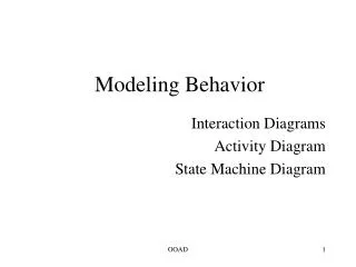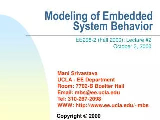
Modeling of Embedded System Behavior
1.14k likes | 1.36k Views
Modeling of Embedded System Behavior. EE298-2 (Fall 2000): Lecture #2 October 3, 2000. Reading. Required [Sgroi00] Sgroi, M.; Lavagno, L.; Sangiovanni-Vincentelli, A. Formal models for embedded system design. IEEE Design & Test of Computers, vol.17, (no.2), IEEE, April-June 2000. p.14-27.

Modeling of Embedded System Behavior
E N D
Presentation Transcript
Modeling of Embedded System Behavior EE298-2 (Fall 2000): Lecture #2October 3, 2000
Reading • Required • [Sgroi00] Sgroi, M.; Lavagno, L.; Sangiovanni-Vincentelli, A. Formal models for embedded system design. IEEE Design & Test of Computers, vol.17, (no.2), IEEE, April-June 2000. p.14-27. • [Douglass98] Douglass, B.P. State machines and statecharts. Embedded Systems Conference West, 1999. http://www.ilogix.com/dev/SMS.zip • Cynapps Cynlib documentation (will need for HW #2)http://chronos.cynapps.com/cgi-bin/download/lrm-index.pl • Recommended • [Harel97] Harel, D.; Gery, E. Executable object modeling with Statecharts. IEEE Computer, July 1997. p. 31-42. • [Edwards97] Edwards, S.; Lavagno, L.; Lee, E.A.; Sangiovanni-Vincentelli, A. Design of embedded systems: formal models, validation, and synthesis. Proceedings of the IEEE, vol.85, (no.3), IEEE, March 1997. p.366-90.
How to Design Embedded Systems? (Wescon 1975) • “...deliberately avoid data processing aides such as assemblers, high-level languages, simulated systems, and control panels. These computer-aided design tools generally get in the way of cost-effective design and are more a result of the cultural influence of data processing, rather than a practical need.” • “It’ s my observation that the bulk of real-world control problems require less than 2,000 instructions to implement. For this size program computer aided design does little to improve the design approach and does a lot to separate the design engineer from intimate knowledge of his hardware.”
Methodical Design of Embedded Systems • Ad hoc approach to design does not work beyond a certain level of complexity, that is exceeded by vast majority of embedded systems • Methodical, engineering-oriented, CAD tool-based approach is essential • specification, synthesis, optimization, verification etc. • prevalent for hardware, still rare for software • One key aspect is the creation of models • concrete representation of knowledge and ideas about a system being developed • model deliberately modifies or omits details (abstraction) but concretely represents certain properties to be analyzed, understood and verified • One of the few tools for dealing with complexity
Abstractions and Models • Foundations of science and engineering • Activities usually start with informal specification • However, soon a need for Models and Abstractions is established • E.g.: Chess and Poker - No Rules, No Games • Connections to Implementation (EE & Hardware) and Application (CS & Software) • Two types of modeling: system structure and system behavior
Good Models • Simple (Ptolemy vs. Galileo) • Amenable for Development of Theory • Has High Expressive Power (A game is interesting only if it has some level of difficulty) • Provides Ability for Critical Reasoning (Science vs. Religion) • Practice is currently THE only serious test of model quality • Executable • Synthesizable
Elements of a Model of Computation: Language • A language is a set of symbols with superimposed syntax and semantics • text-based, visual • Syntax: Rules for combining symbols • well structured, intuitive • Semantics: Rules for assigning meaning to symbols and combinations of symbols • without a rigorous semantic definition, precise model behavior over time is not well defined • full executability and automatic h/w or s/w synthesis is impossible
Semantics and Model of Computation • Operational Semantics (Turing Machine): Which action can be taken by fully defined abstract machine • Denotational Semantics (Scott & Strachey): Meaning is defined in terms of relations • Model of Computation: How the machine can behave or what types of relationship are possible; May include communication style, aggregation, hierarchy, ...
Design and Model of Computation • A design is a system of atomic components • The model of computation defines the behavior and interaction of atomic components • Model Generality / Efficiency of Design Trade-off • Models are easy to define; It is difficult to see their limitations and eventual Effectiveness
Classical CS: Models forGeneral-Purpose Computing • Turing Machine, Post Machine, Universal Register Machine • RAM (von Neuman) => Algorithms and Computational Complexity • Algol, FORTRAN, Lisp, C, C++ • CSP - Communicating Sequential Processes - C.A.R. Hoare • CCS - Calculus of Communicating Systems - R. Milner
Behavior Modeling for Embedded Systems • Function: what does the system do • in non-real-time systems, this is sufficient • Time: meet temporal contract with the environment • temporal behavior important in real-time systems, as most embedded systems are • simple metric such as throughput, latency, jitter • more sophisticated quality-of-service metrics Computation model must support description of both functional and temporal behavior
Structure Modeling for Embedded Systems • Embedded systems often have complex high-level run-time structures • e.g. redundancy structure in a fault-tolerant system • represent the “architecture core” • Topological relationship between individual entities or objects • Peer relationships between communicating objects • Containment relationships • Layering relationships • Dynamic run-time structures
Infrastructure Modeling for Embedded Systems • ES are more constrained than general-purpose systems • e.g. need for timeliness, low-power etc. • Models must allow for early and accurate predictions of key attributes of the actual systems • response times, throughput, availability etc. • finite capacities of underlying computing resources • many techniques developed over the years • schedulability analysis, queuing theory • Need to model not only the behavior and structure of the computation, but also the engineering infrastructure • physical devices: processors, networks, busses etc. • logical devices: tasks, locks, queues, OS services etc. • Resource modeling essential both for accuracy and for systems with application-defined resource management
Popular Computation Models for Embedded Systems • Communicating Finite State Machines • Synchronous / Reactive • Dataflow • Process Networks • Rendezvous-based Models (CSP) • Petri Nets • Tagged-Signal Model • Object-oriented Models • Heterogeneous Models
Graphs as an Abstract Syntax for Models • Graph = <Nodes, Arcs> • Many computation models are obtained by ascribing specific interpretations (semantics) to the nodes and arcs, and sometimes by constraining the structure of the graph • e.g.: Petri nets, Data flow, FSM • Hierarchical graphs offer a useful visual representation
Finite State Machines • FSM is a mathematical model of a system that attempts to reduce model complexity by assuming: • system can be in a finite # of conditions called states • system behavior within a given state is essentially identical • system resides in states for significant periods of time • system may change states only in a finite # of well-defined ways, called transitions • transitions are the response of the system to external or internal events • Functions or operations called actions my be executed when the transition is taken, a state is entered, or a state is exited • implemented by an internal or external datapath or object’s operations • transitions and actions take (approximately) zero time, i.e. instantaneous • “synchronous” • events not permitted in a state are ignored or result in error or queued • FSM = (Inputs, Outputs, States, InitialState, NextState, Outs) • Often suitable for controllers, protocols etc. • Not Turing Complete, but more amenable to analysis • Rarely suitable for Memory and Datapaths
Source: B. P. Douglass & iLogix FSM Examples Elevator Control
Source: B. P. Douglass & iLogix More Complex FSM • Reliable transmission service for a protocol stack • A message is sent that requires thereceiver to ACK • If an ACK doesn’t occur, retransmit • If the message is transmitted 5 times without ACK, inform the sender
Source: B. P. Douglass & iLogix Protocol Controller FSM
FSM Example • Informal specification if driver turns on the key and does not fasten seat belt within 5 seconds then sound the alarm for 5 seconds or until driver fastens the seat belt or turns off the key • Formal representation Inputs = {KEY_ON, KEY_OFF, BELT_ON, BELT_OFF, 5_SECONDS_UP, 10_SECONDS_UP Outputs = {START_TIMER, ALARM_ON, ALARM_OFF} States = {Off, Wait, Alarm} Initial State = off NextState: CurrentState, Inputs -> NextState e.g. NextState(WAIT, {KEY_OFF}) = OFF Outs: CurrentStae, Inputs -> Outputs e.g. Outs(OFF, {KEY_ON}) = START_TIMER
Non-Deterministic FSM • A FSM is said to be non-deterministic when the NextState and Outs functions may be RELATIONs (instead of functions) • Non-determinism can be user to model • unspecified behavior • incomplete specification • unknown behavior • e.g., the environment model • abstraction • (the abstraction may result in insufficient detail to identify previously distinguishable situations)
Source: B. P. Douglass & iLogix Mealy-Moore FSMs • The set of states define the state space • State space are flat • all states are at the same level of abstraction • all state names are unique • State models are single threaded • only a single state can be valid at any time • Mealy state models: all actions are in transitions • Moore state models: all actions are upon state entry
Source: B. P. Douglass & iLogix Retrigerrable One-shot Timer
Source: B. P. Douglass & iLogix Problems with Conventional FSM • Scalability due to lack of metaphor for decomposition • No concurreny support • No support for orthogonal connections
Source: B. P. Douglass & iLogix Scalability
Source: B. P. Douglass & iLogix Scalability
Source: B. P. Douglass & iLogix Concurrency • Problem: • a device can be in states • Off, Starting-up, Operational, Error • And, can be running from • mains, battery • How to arrange these states?
Source: B. P. Douglass & iLogix Concurrency • Following are different states in Mealy/Moore view: • Operation with battery • Operation with mains • Leads to state explosion • Solution? • Allow states to operate concurrently
Source: B. P. Douglass & iLogix Mealy-Moore Solution
Source: B. P. Douglass & iLogix Concurrent State Model Solution
Source: B. P. Douglass & iLogix Orthogonal Components How do you draw the state of this object?
Source: B. P. Douglass & iLogix Approach 1: Enumerate All
Source: B. P. Douglass & iLogix Approach 2
Harel’s StateCharts: Extension of Conventional FSMs • Conventional FSMs are inappropriate for the behavioral description of complex control • flat and unstructures • inherently sequential in nature • give rise to an exponential blow-up in # of states • small system extensions cause unacceptable growth in the number of states to be considered • StateCharts support: • repeated decomposition of states into AND/OR sub-states • nested states, concurrency, orthogonal components • actions (may have parameters) • activities (functions executed as long as state is active) • guards • history • a synchronous (instantaneous broadcast) comm. mechanism
Features of StateCharts • Nested states and hierarchy • Improves scalability and understandability • helps describing preemption • Concurrency - two or more states can be viewed as simultaneously active • Nondeterminism - there are properties which are irrelevant
Source: B. P. Douglass & iLogix Basic Harel Syntax
State Decomposition • OR-states have sub-states that are related to each other by exclusive-or • AND-states have orthogonal state components (synchronous FSM composition) • AND-decomposition can be carried out on any level of states • more convenient than allowing only one level of communicating FSMs • Basic States: no sub-states (bottom of hierarchy) • Root State: no parent states (top of hierarchy)
e S f V g[c] f T h StateChart OR-decomposition U e S V f g[c] T h
StateChart AND-decomposition V,W h k U g V,Z S T Z V,Y k V e m,p e e g W f h e f [in(Y)] g X,Z X,Y Y X m e e k h X,W e p p e n n p m,p R Q R Q p
StateCharts Syntax • The general syntax of an expression labeling a transition in a StateChart is n[c]/a, where • n is the event that triggers the transition • c is the condition that guards the transition(cannot be taken unless c is true when e occurs) • a is the action that is carried out if and when the transition is taken • Alternative: name(params)[guards]^event_list/action_list • Event list, aka propagated transitions, is a list of transitions that occur in other concurrent state machines because of this transitions • For each transition label, event condition and action are optional • an event can be the changing of a value • standard comparisons are allowed as conditions and assignment statements as actions
StateCharts Actions and Events • An action a on the edge leaving a state may also appear as an event triggering a transition going into an orthogonal state • executing the first transition will immediately cause the second transition to be taken simultaneously • Actions and events may be associated to the execution of orthogonal components: • action start(A) causes activity A to start • event stopped(B) occurs when activity B stops • entered(S), exited(S), in(S) etc.
Source: B. P. Douglass & iLogix Order of Nested Actions • Executed from outermost – in on entry • Executed from innermost – out on exit
Source: B. P. Douglass & iLogix History • The history annotation H means that the state “remembers” the substate and returns to it as the default • Can also work with an initial state indicator
Source: B. P. Douglass & iLogix Conditional Transitions
Another Example of the Power of StateChart Formalism reset/ Uninitialized ackB/ • Conflicting function & control behaviors • Function: primary service of the entity • Control: actions performed within the system context • Solutions: single automaton, two peer concurrent states ReadyToSendA send/^A reset/ data/ data/ Initialized Error SendingA SendingB stop/ start/ Operational ReadyToSendB error/ send/^B ackA/
Source: B. P. Douglass & iLogix Example: Jolt Cola Machine
The Combined State Machine in StateChart Formalism reset/ Uninitialized reset/ data/ data/ Initialized Error stop/ start/ Operational error/ ackB/ ReadyToSendA send/^A SendingA SendingB ReadyToSendB send/^B ackA/
Source: B. P. Douglass & iLogix Example: Coin Receptacle FSM
Source: B. P. Douglass & iLogix Substate: Issuing Can