Download
1 / 25

E N D
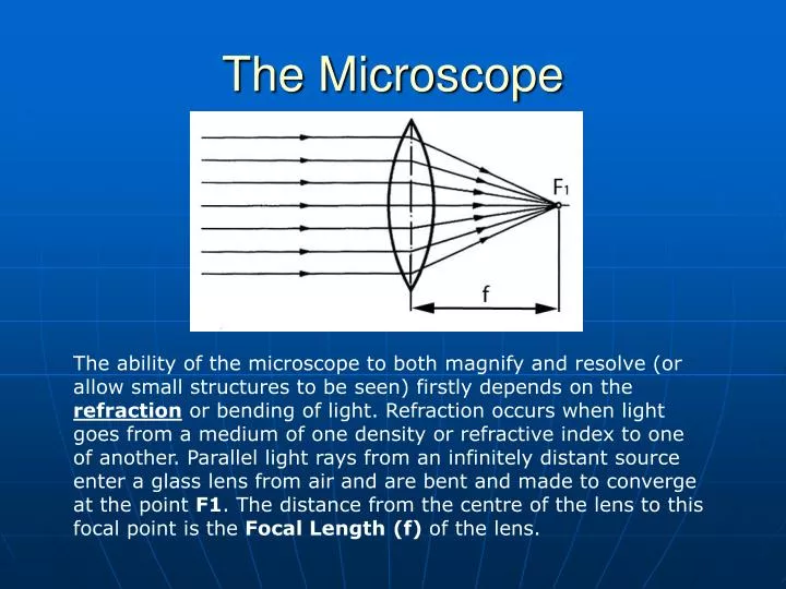
The Microscope The ability of the microscope to both magnify and resolve (or allow small structures to be seen) firstly depends on the refraction or bending of light. Refraction occurs when light goes from a medium of one density or refractive index to one of another. Parallel light rays from an infinitely distant source enter a glass lens from air and are bent and made to converge at the point F1. The distance from the centre of the lens to this focal point is the Focal Length(f) of the lens.
The Microscope The amount of refraction that occurs depends on the difference in Refractive Index of the two media or materials and is described by Snell's law:η1 sin θ1 = η2 sin θ2 The refractive index (η) equals the speed of light in vacuum divided by its speed in the material in question.
The Microscope The exact refractive index for a given material varies with the color or wavelength of light. This explains dispersion, or the ability of a prism to separate out the deferent colors of light:
The Microscope Unfortunately, an image made by a single lens suffers from a number of optical defects. These can include: chromatic aberration, resulting in different wavelengths or colors of light being focused at different distances; coma, resulting in the images of structures out from the center being smeared outwards; spherical aberration, resulting in light passing through the lens center being focused at a different distance to light passing through the outer portion of the lens;
The Microscope In order to combat these defects and produce sharp images, microscope objectives and eyepieces are far more complex and are comprised of multiple lenses made of glass with differing refractive indices. Microscope objectives come in several grades of correction. The left lens is an achromat and is corrected for two colors of light, red and blue, but it still suffers from chromatic aberration in the green region. The apochromat in the middle is corrected for three colors, red, green and blue. On the right the plan achromat is not fully corrected for color but is corrected for spherical aberration and it has a flat field which is particularly important for photography.
The Microscope While the power of a lens indicates the magnification it gives, the numerical aperture gives a relative indication of its resolving power, which is more important than magnification. Bigger is not always better, especially when it comes to magnification, unless it is accompanied by increased resolution of fine detail. The final magnification will be the product of the objective magnification, the eyepiece magnification and perhaps other factors such as the tube factor, the nose piece factor and the camera factor. An old rule of thumb says that the final image magnification should not be more than 1000 times the numerical aperture of the lens used .
The Microscope The numerical aperture, or N.A., of an objective results from the sine of half of the entrance angle of the light cone (shown asu'in the figure below) multiplied by n, the refractive index of the medium between the cover slip and the objective. When a lens is designed to be used dry n = 0 but when a lens is intended to be joined to the prep with immersion oil (oel) the refractive index is 1.515. Numerical aperture generally increases with magnification and/or degree of optical correction. N.A. = n*sin u'
The Microscope The basic light path of the microscope can be clearly seen at the left. Light from the bulb in the base is focused by the collector lenses in the base and sent upward, via a mirror or prism, as an illuminating cone of light which fills the substage condenser with light. The condenser then focuses the light and the image of the fields diaphragm on the specimen. If the aperture diaphragm is set properly the emerging light will fill the objective and give maximum resolution. bulb
The Microscope The preliminary image produced by the objective is deflected by the prism into the eyetubes and then it is further magnified by the eyepieces which project the image into the eye or, if fitted, into the camera.
The Microscope This is a schematic of the optics and light paths of the microscope. The condenser focuses the image of the field diaphragm into the specimen plane and the plane of the eyepiece field stop. It also focuses the filament of the lamp into the plane of the aperture diaphragm and the objective exit pupil. The objective produces a primary or intermediate image of the specimen which is further magnified by the eyepiece and projected into the eye or camera.
The Microscope The condenser plays a critical role in image formation. Highly corrected condensers are complex and are made of a number of lenses as seen below. Like a microscope objective, a condenser has a numerical aperture and it should equal or better that of the highest magnification objective being used. The wavelength of light used (which can be selected by a filter), the objective numerical aperture and the condenser numerical aperture all affect the resolution of the instrument.
The Microscope • There are six basic types of microscopes used in the modern crime laboratory: • The Compound Microscope • The Comparison Microscope • The Stereoscopic Microscope • The Polarizing Light Microscope • The Microscpectrophotometer • The Scanning Electron Microscope (SEM) • The first five involve the use of focused light to achieve image magnification. The last (SEM) involves the use of focused electrons to achieve a magnified image. This allows for magnification far beyond what is available through visible light microscopes.
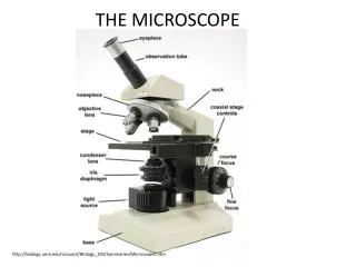
The Microscope • Most of the initial discussion of microscope optics was made for the compound microscope. As described the main parts of a compound microscope are: • The base • The arm • The stage • The tube • Coarse adjust • Fine adjust • Illuminator • Condenser • Objective lens • Eyepiece lens
The Microscope A comparison microscope is a device used to observe side-by-side specimens. It consists of two microscopes connected to an optical bridge, which results in a split view window.
The Microscope The idea behind the comparison microscope is simple. Two microscopes are placed next to each other and the optical paths of each microscope are connected together by the optical bridge.
The Microscope The stereomicroscope is the most frequently used microscope in the crime lab. It allows a 3-dimensional view of objects at high magnification (something you can’t get using a magnifying glass). The stereomicroscope is the primary tool for characterizing physical evidence as diverse as paint, soil, gunpowder residues and marijuana.
The Microscope Stereoscopic Vision
The Microscope http://www.microscopyu.com/tutorials/flash/smz1500/index.html
The Microscope The polarizing light microscope is used to study materials that polarize light. Often this characteristic is unique to a particular material such as crystals in soil or fibers. By shining polarized light through a specimen, one can detect the degree to which it further polarizes light generating a birefringence.
The Microscope Natural sunlight and almost every other form of artificial illumination transmits light waves whose electric field vectors vibrate in all perpendicular planes with respect to the direction of propagation. When the electric field vectors are restricted to a single plane by filtration, then the light is said to be polarized with respect to the direction of propagation and all waves vibrate in the same plane.
The Microscope Polarized light coming up off the horizontal surface of a highway is often termed glare and can be easily demonstrated by viewing the distant part of a highway on a sunny day. Light reflected by the flat surface of a highway is partially polarized with the electric field vectors vibrating in a direction that is parallel to the ground. This light can be blocked by polarizing filters oriented in a vertical direction with a pair of polarized sunglasses.
The Microscope Polarizing microscopy provides a vast amount of information about the composition and three-dimensional structure of a variety of samples. Observations under plane-polarized light (Figure 9(a)) reveal refractive index differences between the fiber and the mountant and the presence of opacifying titanium dioxide particles. The image under crossed polars (Figure 9(b)) shows third order polarization colors and their distribution across the fibers indicates that this is a cylindrical and not a lobate fiber useful in predicting mechanical strength. The use of the quartz wedge (Figure 9(c)) enables the determination of optical path differences for birefringence measurements.
The Microscope The microspectrophotometer combines the latest technologies to allow the user to measure UV-visible-NIR range transmission, absorbance, reflectance, emission and fluorescence spectra of samples as small as one micron. One can look at a crystal through the microscope and, at the same time, do a spectrophotometric analysis of the crystal to determine what it is. It’s especially useful for drugs and explosives.
The Microscope The Scanning Electron Microscope 1)The "Virtual Source" at the top represents the electron gun, producing a stream of monochromatic electrons. 2)The stream is condensed by the first condenser lens (usually controlled by the "coarse probe current knob"). This lens is used to both form the beam and limit the amount of current in the beam. It works in conjunction with the condenser aperture to eliminate the high-angle electrons from the beam 3)The beam is then constricted by the condenser aperture (usually not user selectable), eliminating some high-angle electrons 4)The second condenser lens forms the electrons into a thin, tight, coherent beam and is usually controlled by the "fine probe current knob" 5)A user selectable objective aperture further eliminates high-angle electrons from the beam 6)A set of coils then "scan" or "sweep" the beam in a grid fashion (like a television), dwelling on points for a period of time determined by the scan speed (usually in the microsecond range) 7)The final lens, the Objective, focuses the scanning beam onto the part of the specimen desired. 8)When the beam strikes the sample (and dwells for a few microseconds) interactions occur inside the sample and are detected with various instruments 9)Before the beam moves to its next dwell point these instruments count the number of interactions and display a pixel on a CRT whose intensity is determined by this number (the more reactions the brighter the pixel). 10)This process is repeated until the grid scan is finished and then repeated, the entire pattern can be scanned 30 times per second. http://www.mos.org/sln/SEM/