Joint Seismic Tomography and Inversion in the Reno/Carson City Area for Enhanced Velocity Modeling
This study aims to develop a comprehensive tomographic velocity model for the Reno/Carson City area, extending to 15 km depth. Using over 200,000 P- and S-wave travel times, 14,000 earthquake events, and 71 seismic stations, we focus on refining hypocenter locations and improving our understanding of velocity structures in this seismically active region. The research incorporates cross-correlation techniques and checkerboard testing to assess model integrity. Key findings indicate low velocity zones in the Reno basin, aligned with known geological features, enhancing our seismic interpretation capabilities.

Joint Seismic Tomography and Inversion in the Reno/Carson City Area for Enhanced Velocity Modeling
E N D
Presentation Transcript
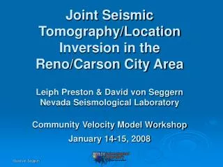
Joint Seismic Tomography/Location Inversion in the Reno/Carson City Area Leiph Preston & David von SeggernNevada Seismological LaboratoryCommunity Velocity Model WorkshopJanuary 14-15, 2008
Goals • Develop a tomographic velocity model in the Reno/Carson City area at kilometer scale to roughly 15 km depth. • Relocate NSL catalog seismicity jointly with tomographic imaging. • Utilize cross-correlation times of P and S waves to constrain the relative hypocenters. • Compare imaging results with other available velocity results.
Catalog Location of EarthquakesUsed for Inversion(1990-2006)
Arrival-Time Residuals From Catalog Residuals are computed with respect to 1-dimensional layered model.
Summary of Input • > 200,000 P and S travel times • > 200,000 cross-correlation times • > 14,000 earthquakes • 23 blasts • 71 stations
Image Parameters • horizontal resolution = 2 km (90 x 91 grid) • vertical resolution = 1 km • 42 depths, from -5 to 36 km, relative to MSL • Vp and Vp/Vs images
Establish Resolving Capability Dependence on Starting Model: We ran cases with various reasonable starting models and found no significant dependency of result on starting velocities. Checkerboard Test: We perturb the final model, recompute travel-times, re-image the velocity model, and see if perturbations are recovered.
Checkerboard Test (Vp) vertical exag. = 3
Imaged Cross-section(Vp): 39.55N Reno Basin vertical exag. = 3
Imaged Cross-section (Vp): -119.75W vertical exag. = 3
Imaged Cross-section (Vp/Vs): 39.55N vertical exag. = 3
Imaged Cross-section (Vp/Vs): 39.25N vertical exag. = 3
Imaged Cross-section (Vp/Vs): -119.75W vertical exag. = 3
How Do We Compare? 2-D Refraction Line Tomography (Louie et al.) 3-D Joint Inversion (This Study)
Original Catalog Epicenters Joint Inversion Epicenters
Caveats With Seismicity Relocation • Many earthquakes are culled out by residual analysis and data requirements during inversion. • Locations trade off with structure in joint inversion. • Nevada seismicity tends to be diffuse, with unclear relation to known fault traces. • Lineations, if present, need to be viewed by zooming plots.
Example of Seismicity Lineation Carson Range ~ 6 - 10 km north of Kings Beach
Summary • A volume in the region 38.5,-121.0 to 40.0,-119.0 down to ~ 15 km depth below MSL was imaged using P and S wave tomography and simultaneous solution for refined hypocenters. • Low velocities exist east of the Sierra Nevada at shallow depths, coinciding with known basins, and especially low in the Reno basin. • The Sierra Nevada crest and westward have high velocities at shallow depth. • Anomalously high Vp/Vs material apparently exists just above the 2003 deep (25-30 km) swarm of earthquakes under north Lake Tahoe.