Composite Construction
Learn about the design and construction guidelines for shear connectors in composite structures, specifications for steel and concrete components, and practical examples.

Composite Construction
E N D
Presentation Transcript
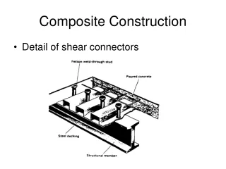
Composite Construction • Detail of shear connectors
Composite Construction PNA in steel PNA in concrete b b a Ycon Ycon C = Ccon+Cst Tst C=T Mn = Cy = Ty b b a C con Ycon y Tst
Composite Construction Ccon = 0.85f’cba T = FyAs Ccon and T can not exceed force carried by studs, ∑Qn ∑Qn =0.85 f’cba Depth of compression block
Composite Members Specificationp. 16.1-40 I3 Flexural Members • Effective Width, b, sum of effective widths for each side of beam center-line, each of which shall not exceed: 1) 1/8 of beam span 2) ½ distance to center-line of adjacent beam 3) distance to edge of slab b b b
Composite Members Specificationp. 16.1-40 I3 Flexural Members (cont.) • Design Strength of Beams with Shear Connectors • - • Strength During Construction • Formed Steel Deck 5a. General hr ≤ 3” wr ≥ 2” shear stud diameter ≤ ¾” shear studs must extend 1½ -in. above top of deck Slab thickness must be ≥ 2” above steel deck
Composite Members Specificationp. 16.1-40 I3 Flexural Members (cont.) • Formed Steel Deck 5b. Deck Ribs Perpendicular to Steel Beam Max shear stud spacing 36 in. Shear stud strength reduction factor – eq. I3-1 ≤0.75 if only single stud in rib Deck must be anchored every 18 in. 5c. Deck Ribs Oriented Parallel to Steel Beam Shear stud strength reduction factor – eq. I3-2 applied if wr/hr ≤1.5 • Design Shear Strength
Composite Members Specificationp. 16.1-40 I5 Shear Connectors – shear studs or channels • Length shear studs, Hs ≥ 4 stud diameters • - • Strength of Stud Shear Connectors Eq. I5-1 modified by reduction factors • - • Required Number of Connectors
Composite Members Specificationp. 16.1-40 I5 Shear Connectors – shear studs or channels • Required Number of Connectors – Number required must be provided from section of maximum bending moment to adjacent section of zero moment. • Shear Connector Placement and Spacing Stud diameter ≤2.5 tf (prevent tear out) Minimum spacings ribs parallel: longitudinal – 6 x stud diameter transverse – 4 x stud diameter ribs perpendicular: 4 x stud diameter (long. and trans.) Maximum spacing 8 x slab thickness
Composite Construction p.5-33 Effective concrete flange force (∑Qn) • Y1 – Distance from PNA to beam top flange • Y2 – Distance from concrete flange force to beam top flange • b – effective width of concrete slab flange • a – effective concrete flange thickness b Ycon a Y2 Y1 PNA
Composite Design Example p. 39 notes Redesign the floor system previously designed (example p. 33), using composite construction. A992 steel and 3500 psi concrete.