Download
1 / 20
260 likes | 759 Views
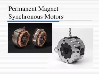
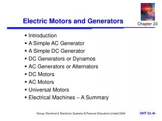
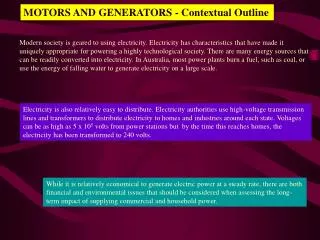
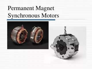
Synchronous Motors and Generators. Synchronous Motors. Constant-speed machine Propulsion for SS “Queen Elizabeth II” 44 MW 10 kV 60 Hz 50 pole 144 r/min. Synchronous Motors (continued). Construction Stator identical to that of a three-phase induction motor – now called the “armature”

E N D
Synchronous Motors • Constant-speed machine • Propulsion for SS “Queen Elizabeth II” • 44 MW • 10 kV • 60 Hz • 50 pole • 144 r/min
Synchronous Motors (continued) • Construction • Stator identical to that of a three-phase induction motor – now called the “armature” • Energize from a three-phase supply and develop the rotating magnetic field • Rotor has a DC voltage applied (excitation) • Rotor could be a permanent-magnet type
Synchronous Motors (continued) • Operation • Magnetic field of the rotor “locks” with the rotating magnetic field – rotor turns at synchronous speed
Salient-Pole Rotor Excitation Windings
Synchronous Motor Starting • Get motor to maximum speed (usually with no load) • Energize the rotor with a DC voltage
Salient-Pole Motor operating at both no-load and loaded conditions Angle δ is the power angle, load angle, or torque angle
Rotating Field Flux and Counter-emf • Rotating field flux f due to magnetic field in the rotor. A “speed” voltage, “counter-emf”, or “excitation” voltage Ef is generated and acts in opposition to the applied voltage. • Ef = nsfkf
Equivalent Circuit of a Synchronous Motor Armature (One Phase)
Phasor Diagram for one phase of a Synchronous Motor Armature
Motor-to-Generator Transition (cont) • Begin with motor driven from the infinite bus and the turbine torque in the same direction as the motor torque. • The motor operates normally, driving the water pump.
Motor-to-Generator Transition (cont) Phasor Diagram VT = Ef + IajXs
Allow the Turbine to take part load Motor becomes a generator as δ becomes > or = zero Excitation voltage is not changed and the vector traces an arc The power angle decreases to zero and then becomes positive
Motor Action Power angle is negative
Motor to Generator Transition Power angle is now = 0
Generator Action Power angle is positive Note: Iacosθi is reversed!
Generator Action (cont) • In order for Ia to reverse direction, voltage Ef must become a source voltage • Ef > VT Ia