Parallel operation of synchronous generators
1.24k likes | 3.31k Views
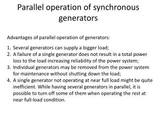
Parallel operation of synchronous generators. Advantages of parallel operation of generators: Several generators can supply a bigger load; A failure of a single generator does not result in a total power loss to the load increasing reliability of the power system;

Parallel operation of synchronous generators
E N D
Presentation Transcript
Parallel operation of synchronous generators • Advantages of parallel operation of generators: • Several generators can supply a bigger load; • A failure of a single generator does not result in a total power loss to the load increasing reliability of the power system; • Individual generators may be removed from the power system for maintenance without shutting down the load; • A single generator not operating at near full load might be quite inefficient. While having several generators in parallel, it is possible to turn off some of them when operating the rest at near full-load condition.
Conditions required for paralleling A diagram shows that Generator 2 (oncoming generator) will be connected in parallel when the switch S1 is closed. However, closing the switch at an arbitrary moment can severely damage both generators!
Conditions required for paralleling If voltages are not exactly the same in both lines (i.e. in a and a’, b and b’ etc.), a very large current will flow when the switch is closed. Therefore, to avoid this, voltages coming from both generators must be exactly the same.
Conditions required for paralleling • Therefore, the following conditions must be met: • The rms line voltages of the two generators must be equal. • The two generators must have the same phase sequence. • The phase angles of two a phases must be equal. • The frequency of the oncoming generator must be slightly higher than the frequency of the running system.
Conditions required for paralleling If the phase sequences are different, then even if one pair of voltages (phases a) are in phase, the other two pairs will be 1200 out of phase creating huge currents in these phases. Solution: swap any two phases of the incoming macnine
Conditions required for paralleling If the frequencies of the generators are different, a large power transient may occur until the generators stabilize at a common frequency. The frequencies of two machines must be very close to each other but not exactly equal. If frequencies differ by a small amount, the phase angles of the oncoming generator will change slowly with respect to the phase angles of the running system. If the angles between the voltages can be observed, it is possible to close the switch S1 when the machines are in phase.
General procedure for paralleling generators • When connecting the generator G2 to the running system, the following steps should be taken: • Adjust the field current of the oncoming generator to make its terminal voltage equal to the line voltage of the system (use a voltmeter). • Compare the phase sequences of the oncoming generator and the running system. This can be done by different ways: • Connect a small induction motor to the terminals of the oncoming generator and then to the terminals of the running system. If the motor rotates in the same direction, the phase sequence is the same; 2) Connect three light bulbs across the open terminals of the switch. As the phase changes between the two generators, light bulbs get brighter (large phase difference) or dimmer (small phase difference). If all three bulbs get bright and dark together, both generators have the same phase sequences.
General procedure for paralleling generators If phase sequences are different, two of the conductors on the oncoming generator must be reversed. 3. The frequency of the oncoming generator is adjusted to be slightly higher than the system’s frequency. 4. Turn on the switch connecting G2 to the system when phase angles are equal. The simplest way to determine the moment when two generators are in phase is by observing the same three light bulbs. When all three lights go out, the voltage across them is zero and, therefore, machines are in phase. A more accurate way is to use a synchroscope – a meter measuring the difference in phase angles between two a phases. However, a synchroscope does not check the phase sequence since it only measures the phase difference in one phase. The whole process is usually automated…
Terminal characteristics of synchronous generators A typical speed vs. power plot A typical frequency vs. power plot shaft speed is linked to the electrical frequency as fe = nmP/120 the power output from the generator is related to its frequency: P = SP (fnl – fsys) Operating frequency of the system Slope of curve, W/Hz
Conditions required for paralleling • Therefore, the following conditions must be met: • The rms line voltages of the two generators must be equal. • The two generators must have the same phase sequence. • The phase angles of two a phases must be equal. • The frequency of the oncoming generator must be slightly higher than the frequency of the running system.
Operation of generators in parallel with large power systems Often, when a synchronous generator is added to a power system, that system is so large that one additional generator does not cause observable changes to the system. A concept of an infinite bus is used to characterize such power systems. An infinite bus is a power system that is so large that its voltage and frequency do not vary regardless of how much real and reactive power is drawn from or supplied to it. The power-frequency and reactive power-voltage characteristics are:
Operation of generators in parallel with large power systems Consider adding a generator to an infinite bus supplying a load. The frequency and terminal voltage of all machines must be the same. Therefore, their power-frequency and reactive power-voltage characteristics can be plotted with a common vertical axis. Such plots are called sometimes as house diagrams.
Operation of generators in parallel with large power systems If the no-load frequency of the oncoming generator is slightly higher than the system’s frequency, the generator will be “floating” on the line supplying a small amount of real power and little or no reactive power. If the no-load frequency of the oncoming generator is slightly lower than the system’s frequency, the generator will supply a negative power to the system: the generator actually consumes energy acting as a motor! Many generators have circuitry automatically disconnecting them from the line when they start consuming energy.
Operation of generators in parallel with large power systems If the frequency of the generator is increased after it is connected to the infinite bus, the system frequency cannot change and the power supplied by the generator increases. Notice that when EA stays constant (field current and speed are the same), EAsin (which is proportional to the output power if VT is constant) increases.
Operation of generators in parallel with large power systems • Summarizing, when the generator is operating in parallel to an infinite bus: • The frequency and terminal voltage of the generator are controlled by the system to which it is connected. • The governor set points of the generator control the real power supplied by the generator to the system. • The generator’s field current controls the reactive power supplied by the generator to the system.
Generators in parallel with other generators of the same size When a generator is working alone, its real and reactive power are fixed and determined by the load. When a generator is connected to an infinite bus, its frequency and the terminal voltage are constant and determined by a bus. When two generators of the same size are connected to the same load, the sum of the real and reactive powers supplied by the two generators must equal the real and reactive powers demanded by the load:
Generators in parallel with other generators of the same size Since the frequency of G2 must be slightly higher than the system’s frequency, the power-frequency diagram right after G2 is connected to the system is shown. If the frequency of G2 is next increased, its power-frequency diagram shifts upwards. Since the total power supplied to the load is constant, G2 starts supplying more power and G1 starts supplying less power and the system’s frequency increases.
Generators in parallel with other generators of the same size • Therefore, when two generators are operating together, an increase in frequency (governor set point) on one of them: • Increases the system frequency. • Increases the real power supplied by that generator, while reducing the real power supplied by the other one. • When two generators are operating together, an increase in the field current on one of them: • Increases the system terminal voltage. • Increases the reactive power supplied by that generator, while reducing the reactive power supplied by the other. If the frequency-power curves of both generators are known, the powers supplied by each generator and the resulting system frequency can be determined.
Generators in parallel with other generators of the same size: Ex Example 4: Two generators are set to supply the same load. Generator 1 has a no-load frequency of 61.5 Hz and a slope sp1 of 1 MW/Hz. Generator 2 has a no-load frequency of 61.0 Hz and a slope sp2 of 1 MW/Hz. The two generators are supplying a real load of 2.5 MW at 0.8 PF lagging. • Find the system frequency and power supplied by each generator. • Assuming that an additional 1 MW load is attached to the power system, find the new system frequency and powers supplied by each generator. • With the additional load attached (total load of 3.5 MW), find the system frequency and the generator powers, if the no-load frequency of G2 is increased by 0.5 Hz.