Download
1 / 30
410 likes | 840 Views
Electric Motors and Generators. Introduction A Simple AC Generator A Simple DC Generator DC Generators or Dynamos AC Generators or Alternators DC Motors AC Motors Universal Motors Electrical Machines – A Summary. Introduction.

E N D
Electric Motors and Generators • Introduction • A Simple AC Generator • A Simple DC Generator • DC Generators or Dynamos • AC Generators or Alternators • DC Motors • AC Motors • Universal Motors • Electrical Machines – A Summary
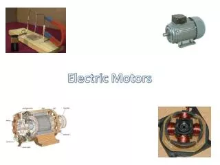
Introduction • In this lecture we consider various forms of rotating electrical machines • These can be divided into: • generators – which convert mechanical energy into electrical energy • motors – which convert electrical energy into mechanical energy • Both types operate through the interaction between a magnetic field and a set of windings
A Simple AC Generator • We noted earlier that Faraday’s law dictates that if a coil of N turns experiences a change in magnetic flux, then the induced voltage V is given by • If a coil of area A rotates with respect to a field B, and if at a particular time it is at an angle to the field, then the flux linking the coil is BAcos, and the rate of change of flux is given by
Therefore this arrangement produces a sinusoidal output as shown below
Wires connected tothe rotating coilwould get twisted • Therefore we usecircular slip ringswith slidingcontacts calledbrushes
A Simple DC Generator • The alternating signal from the earlier AC generator could be converted to DC using a rectifier • A more efficient approach is to replace the two slip rings with a single split slip ring called a commutator • this is arranged so that connections to the coil are reversed as the voltage from the coil changes polarity • hence the voltage across the brushes is of a single polarity • adding additional coils produces a more constant output
The ripple can be further reduced by the use of a cylindrical iron core and by shaping the pole pieces • this produces anapproximatelyuniform field in thenarrow air gap • the arrangementof coils and coreis known as thearmature
DC Generators or Dynamos • Practical DC generators or dynamos can take a number of forms depending on how the magnetic field is produced • can use a permanent magnet • more often it is generated electrically using field coils • current in the field coilscan come from an external supply • this is known as a separately excited generator • but usually the field coils are driven from the generator output • this is called a self-excited generator • often use multiple poles held in place by a steel tube called the stator
Field coil excitation • sometimes the field coils are connected in series with the armature, sometimes in parallel (shunt) and sometimes a combination of the two (compound) • these different formsproduce slightlydifferentcharacteristics • diagram hereshows ashunt-woundgenerator
DC generator characteristics • vary slightly between forms • examples shown here are for a shunt-wound generator
AC Generators or Alternators • Alternators do not require commutation • this allows a simpler construction • the field coils are made to rotate while the armature windings are stationary • Note: the armature windings are those that produce the output • thus the large heavy armature windings are in the stator • the lighter field coils are mounted on the rotor and direct current is fed to these by a set of slip rings
As with DC generators multiple poles and sets of windings are used to improve efficiency • sometimes three sets of armature windingsare spaced 120 apart around the stator to forma three-phase generator • The e.m.f. produced is in sync with rotation of the rotor so this is a synchronous generator • if the generator has a single set of poles the output frequency is equal to the rotation frequency • if additional pole-pairs are used the frequency is increased accordingly
Example – see Example 23.2 from course text A four-pole alternator is required to operate at 60 Hz. What is the required rotation speed? A four-pole alternator has two pole pairs. Therefore the output frequency is twice the rotation speed. Therefore to operate at 60Hz, the required speed must be 60/2 = 30Hz. This is equivalent to 30 60 = 1800 rpm.
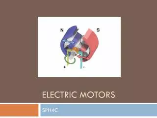
DC Motors • When current flows in a conductor it produces a magnetic field about it - as shown in (a) below • when the current-carrying conductor is within an externally generated magnetic field, the fields interact and a force is exerted on the conductor - as in (b)
Therefore if a conductor lies within a magnetic field: • motion of the conductor produces an electric current • an electric current in the conductor will generate motion • The reciprocal nature of this relationship means that, for example, the DC generator above will function as a DC motor • although machines designed as motors are more efficient in this role • Thus the four-pole DC generator shown earlier could equally well be a four-pole DC motor
DC motor characteristics • many forms – each with slightly different characteristics • again can be permanent magnet, or series-wound, shunt-wound or compound wound • figure below shows a shunt-wound DC motor
AC Motors • AC motors can be divided into two main forms: • synchronous motors • induction motors • High-power versions of either type invariably operate from a three-phase supply, but single-phase versions of each are also widely used – particularly in a domestic setting
Synchronous motors • just as a DC generator can be used as a DC motor, so AC generators (or alternators) can be used as synchronous AC motors • three phase motorsuse three sets of stator coils • the rotating magnetic field drags the rotor around with it • single phase motors require some starting mechanism • torque is only produced when the rotor is in sync with the rotating magnetic field • notself-starting – may be configured as an induction motor until its gets up to speed, then becomes a synchronous motor
Induction motors • these are perhaps the most important form of AC motor • rather than use slip rings to pass current to the field coils in the rotor, current is induced in the rotor by transformer action • the stator is similar to that in a synchronous motor • the rotor is simply a set of parallel conductors shorted together at either end by two conducting rings
In a three-phase induction motor the three phases produce a rotating magnetic field (as in a three-phase synchronous motor) • a stationary conductor will see a varying magnetic field and this will induce a current • current is induced in the field coils in the same way that current is induced in the secondary of a transformer • this current turns the rotor into an electromagnet which is dragged around by the rotating magnetic field • the rotor always goes slightly slower than the magnetic field – this is the slip of the motor
In single-phase induction motors other techniques must be used to produce the rotating magnetic field • various techniques are used leading to various forms of motor such as • capacitor motors • shaded-pole motors • such motors are inexpensive and are widely used in domestic applications
Universal Motors • While most motors operate from either AC or DC, some can operate from either • These are universal motors and resemble series-wound DC motors, but are designed for both AC and DC operation • typically operate at high speed (usually > 10,000 rpm) • offer high power-to-weight ratio • ideal for portable equipment such as hand drills and vacuum cleaners
Electrical Machines – A Summary • Power generation is dominated by AC machines • range from automotive alternators to the synchronous generators used in power stations • efficiency increases with size (up to 98%) • Both DC and AC motors are used • high-power motors are usually AC, three-phase • domestic applications often use single-phase induction motors • DC motors are useful in control applications
Key Points • Electrical machines include both generators and motors • Motors can usually function as generators, and vice versa • Electrical machines can be divided into AC and DC forms • The rotation of a coil in a uniform magnetic field produces a sinusoidal e.m.f. This is the basis of an AC generator • A commutator can be used to produce a DC generator • The magnetic field in an electrical machine is normally produced electrically using field coils • DC motors are often similar in form to DC generators • Some forms of AC generator can also be used as motors • The most widely used form of AC motor is the induction motor