Download
1 / 15
150 likes | 318 Views
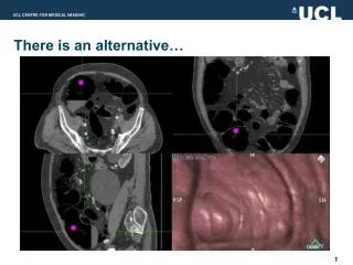
An alternative spectrograph mount. Bruce C. Bigelow University of Michigan Department of Physics 5/14/04. Spectrograph mount. Objectives: Design a high-performance spectrograph mount to FP high stiffness / high first resonance low launch stresses, small deflections

E N D
An alternative spectrograph mount Bruce C. Bigelow University of Michigan Department of Physics 5/14/04
Spectrograph mount Objectives: • Design a high-performance spectrograph mount to FP • high stiffness / high first resonance • low launch stresses, small deflections • simple, clear interface to focal plane (ICD) • ease installation and removal of spectro. • minimize mass, part count • Performance goals (from Besuner, 4/29/04) • first resonance above 100 Hz • material failure (yield) above ~40g • acceptable focal plane distortion for DT = 160K
Spectrograph mount Design features: • Truss structure, Invar tubes • 2:1 Truss geometry • Horizontal translations, no tilts • Attaches to common focal plane mounting points • Essentially no loads carried by focal plane assembly • Simple interface to spectrograph • 3 discrete support points, or round flange • Supports spectrograph load near center of mass • minimizes moment loads • Simple interface to FP (mount points, cylindrical volumes) • Spectrograph and mount easily separate from FP or each other
Spectro mount on FP 2:1 truss geometry – inner to outer triangle dimensions
Spectro mount on FP FP assembly with spectro structure attached
Spectro installed Ease of access to detector connections FP assembly with spectrograph included (note redundant str.)
Spectrograph mount FE Analyses: • General • Spectro mass modeled as 10Kg Invar cylinder • Invar spectrograph mounting truss • 7075 Alum. focal plane baseplate (extreme case) • Static • Strut geometry: 25 mm OD, 2 mm wall thickness • 40 G transverse acceleration (launch orientation) • Dynamic • First 10 mode shapes, frequencies • Thermal • Delta T = -160K • Stresses and deflections
Static FEA Deflections: Ay = 40G, Dy = 137 microns (0.005”)
Static FEA Stress: Ay = 40G, s = 23.7 MPa (3436 Psi) (250 MPa yield)
Dynamic FEA • First 6 freq: • 413 Hz • 415 Hz • 416 Hz • 470 Hz • 478 Hz • 490 Hz First resonance = 413 Hz, transverse mode
Thermal FEA Elements: Purple – Al 7075, Red, Blue - Invar
Thermal FEA Axial deflection for -160 K = 940 microns (0.037”), due to Al baseplate (dl = 50 microns for 0.25m of Invar). Much less for MZT baseplate, can be thermally compensated with strut materials.
Thermal FEA Stress for -160 K = 67.4 MPa (9773 Psi) (worst case with Al baseplate, simple model)
Spectrograph mount Conclusions: • Truss structure meets all design objectives: • high stiffness, high resonance • low stresses • simple, clear interface to FP • easy installation, removal, and access to FP • minimum part count, low mass • Truss structure meets all performance goals: • first resonance above 400 Hz (100 Hz goal) • material failure safety factor of 10 at 40g • minimal or no distortion of focal plane (independent) • Truss is a viable alternative to flexure mount