Heat
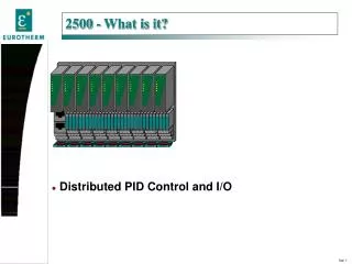
Light 1. Light 2. Servo. Main Lamp. Aux Lamp. Main Gas. Aux Gas. Reset. Inner Temp. Main Fan. Presure. Main Air. Aux Fan. Aux Air. Supply. Valve. Fridge. Load. Lower. Hold. Run. Temp. Input. Raise. Heat. Cool. 2500 - What is it?. Distributed PID Control and I/O.

Heat
E N D
Presentation Transcript
Light 1 Light 2 Servo Main Lamp Aux Lamp Main Gas Aux Gas Reset Inner Temp Main Fan Presure Main Air Aux Fan Aux Air Supply Valve Fridge Load Lower Hold Run Temp Input Raise Heat Cool 2500 - What is it? Distributed PID Control and I/O
Distributed I/O and EUROTHERM PID Light 1 Light 2 Servo Main Lamp Aux Lamp Main Gas Aux Gas Reset Inner Temp Main Fan Presure Main Air Aux Fan Aux Air Supply Fridge Valve Load Hold Lower Run Temp Input Raise Heat Cool 2500 - Eurotherm Distributed Control & I/O PC300 LCM 2700 (in future) 2900 SCADA PLC
4, 8, 16 way bases 2, 4 or 8 loops per base AI2, AI3, AI4, AO2, RLY4, LGC4, DI4, DI8 modules iTools Windows Configurator Light 1 Light 2 Servo Main Lamp Aux Lamp Aux Gas Main Gas Reset Inner Temp Main Fan Presure Main Air Aux Fan Aux Air Fridge Supply Valve Load Hold Lower Run Temp Input Raise Heat Cool 2500 Features Hot swap I/O module Expandable Three Year Warranty
Up to 8 loops per base Each loop can be: - Single PID loop - Ratio control - Cascade pair - Overide control With standard analogue output OR TPO outputs OR Raise / Lower output for valve positioning. Control Loops User Wiring User Variables: 8 real values Analogue functions: 16 e.g. *,/,+,-, sample and hold, and lots more. Digital functions: 16 e.g. OR,AND,XOR,LATCH<,>
Light 1 Light 2 Servo Main Lamp Aux Lamp Aux Gas Main Gas Reset Inner Temp Main Fan Presure Main Air Aux Fan Aux Air Fridge Supply Valve Load Hold Lower Run Temp Input Raise Heat Cool 2500 DIN Rail Controller • Executes 2 loops @ 110mSec, 8 loops @ 220mS • Soft User “Wiring”. • Configuration by “iTools” on a PC Plug-In I/O Modules circuitry - low cost - optional fuses - SW configured * dual analogue input * dual analogue output * quad digital input * quad logic out * quad relay output Plug-in I/O Controller- • H3048 based (32bit) - 2 loop control - cascade control - Soft Wiring - ST, Gain sched. etc - I/O DIN-rail or wall mount I/O Network MODBUS Profibus-DP …... I/O Bases From 4 up to a maximum of 16 modules Terminals One for every wire Plug in terminal Units With or without fuses
Light 1 Light 2 Servo Main Lamp Aux Lamp Main Gas Aux Gas Reset Inner Temp Main Fan Presure Main Air Aux Fan Aux Air Supply Valve Fridge Load Lower Hold Run Temp Input Raise Heat Cool 2500 DIN Rail Controller The unit is supplied as follows: • Base, 2500B • Controller Module, 2500C • I/O Modules, 2500M • Terminal Strips, 2500T • Power Supply, 2500P I/O Modules
An external 24 VDC power supply is required. The voltage range 18 VDC to 28 VDC A system with 4 analog inputs, 4 analog outputs, 4 digital inputs and 4 digital outputs requires 0.5 amps. Eurotherm offers 3 24VDC supplies 2.5 amp (60 watt 5 amp (120 watt) 10 amp (240 watt) The Eurotherm supply has: Will hold up power for 20-37 ms. On power fail Has watchdog relay Power supply
Light 1 Light 2 Servo Main Lamp Aux Lamp Main Gas Gas Reset Inner Temp Main Fan Pressure Main Air Supply Fridge Fan Valve Air Load Hold Lower Run Temp Input Raise Heat Cool 2500 - Base Terminal units snap in Modules changeable “live” (except relay) DIN rail mount 4, 8, or 16 way units
One for each module including IOC Three Analog input terminal units, TC DC/ RTD ma. Fuses available for relay output (July 99) One terminal for every wire Terminal Unit, 2500T
Currently 4 variants Data acquisition only Data acquisition with Application Blocks 2, 4 or 8 PID loops 2, 4 or 8 PID loops with Application Blocks IOC does all calculations; PID, Application Blocks, communications Light 1 Light 2 Servo Main Lamp Aux Lamp Main Gas Aux Gas Reset Inner Temp Main Fan Presure Main Air Aux Fan Aux Air Supply Valve Fridge Load Lower Hold Run Temp Input Raise Heat Cool The Control Module (IOC) The IOC goes in the left most slot
LED Color ON ALL OFF * Green Normal operation Self test failed on S Yellow Stand-by (future) power up C Yellow Configuration * S C X 2500 IOC Status LED’s
Will appear at both Address 255 & the address set by the address switches Addresses between 65 and 254 software settable only with all switches set to zero * RJ11 Socket on the IOC RS232 port Max baud rate is 9600 Using this socket outs the IOC in Config. mode S RJ45 Socket on the Terminal Unit RS 485 Max baud rate is 32,400 Terminator required in the last socket C X 2500 IOC Configuration port
2900 or Computer Terminator RJ45 Comms Line Terminator Communications- (Control Module) The 2500 system allows communications using either MODBUS or PROFIBUS The MODBUS addresses are selected by the DIL switch on the termination assembly beneath the IOC Address 05, Parity off
Zirconia Probe hi Z input 3-wire Pt100 4-wire Pt100 Dual mA Dual T/C H1 H1 H1 H2 H2 H2 H1 H2 B1 I2 B2 B2 B1 I2 B1 I2 B2 I1 I1 I1 B1 I2 B2 I1 C2 A1 A1 C2 C2 A1 C1 A2 C1 A2 C1 A2 C2 A1 1+ 1- C1 A2 2+ 2- C1 A1 I1 A1 I1 C1 A1 C1 B1 C1 A1 PRT PRT mA Functional insulation * Zi A2 A2 I2 I2 B2 C2 C2 C2 C2 A2 A2 PRT PRT Zi mA 2500M/AI2 2-channel Analogue input Module Low level range High level range Resolution Linearity Calibration accuracy User calibration Thermocouple types Potentiometer input -100 to +100mV 0-20mA or 0-10Vdc <2uV for low level inputs <0.2mV for high level inputs Better than 0.2OC +/- 1OC or +/- 0.2% of reading Low and high offsets can be applied All common types, RTD, Zirconia probe 330 to 15Kohm Dual V or mV H1 H2 B2 B1 I2 I1 A1 C2 C1 A2 C1 A1 V C2 A2 V
Three Channel Milli-amps (mA) Isolated 24v Supply Two wire Tx, Three Channel Milli-amps (mA) Remote powered two wire Tx P1 P2 P3 P1 P2 P3 C1 C2 C3 C1 C2 C3 I2 I3 I1 I2 I3 I1 C1 C1 I1 P1 mA mA C2 C2 C3 C3 I3 P2 I2 P3 mA mA mA mA 2500M/AI3 3-Channel high level Analogue Input Modules Input range Resolution Linearity Calibration accuracy User calibration Power Supply -20mA to +20mA < 0.5uA <0.003% of range +/- 0.01% of range, 0.05% of reading Low and high offsets can be applied nominal 24Vdc @ 25mA for two wire transmitters Functional insulation *
1+ 2- 1- 2+ 1- 1- 1+ 1+ V V 2- 2+ 1- 1+ R R mA mA 2500M/AO2 2-channel Analogue output Module Range Resolution Analogue output functions Output Load 0-20mA, 0-10VDC (isolated) 1 part in 10,000 Selectable using User Wiring Up to 600 ohms
Contact Inputs 1 4 2 3 C C C C V+ C V+ C V+ C V+ C + 18-30Vdc - C C 1 2 C C 3 4 2500M/DI4 4-channel Digital Input Module Contact closure inputs 24Vdc Logic inputs Digital input functions Switching voltage: As supply (18 to 30Vdc) Switching current: 10mA (Initial, 1mS 100mA sink for clean switching) (isolated from system, shared common) Off state: -3 to 5Vdc @ <-0.4mA On state: 10.8 to 30Vdc @ 2.5mA (isolated from system, shared common) Selectable using User Wiring 24Vdc Logic Inputs 1 4 2 3 C C C C C V+ V+ C Link for voltage mode C 1 C 2 + + - - 3 C 4 C + + - -
1 1 7 7 3 3 5 5 C3 C3 C4 C4 C2 C2 C1 C1 2 2 4 4 6 6 8 8 1 2 3 C2 4 C1 1 C1 2 3 C2 4 + + - + - + Functional isolation 5 C3 6 7 C4 8 C3 5 6 7 C4 8 + + - + - + Logic Inputs Contact Inputs 2500M/DI8 8-channel Digital Input Module Open circuit voltage: 24V dc nominal Short circuit current: 10mA Off state: <100ohm input resistance On state: >28Kohm input resistance Off state: -3 to 5Vdc On state: 10.8 to 30Vdc @ <10mA Selectable using iTools Contact closure inputs Logic inputs (current sinking) Digital input functions
B1 B4 B2 B3 A2 A3 A4 A1 C4 B1 B3 B2 A4 C4 A1 A3 A2 B4 2500M/DO4 4-channel Relay output Module • Max: 2A, 264Vac resistive • Min: 12Vdc/ac, 100mA (Will work with 2500 logic inputs) • Time Proportioning control, • Motorised valve control • Alarms and events Switching current & volts Digital output functions (3 n/o, 1 c/o relay)
2500M/DO4/LOGIC 4-channel mA logic output2500M/DO4/24V 4-channel voltage logic output Quad 10mA logic output Quad 24Vdc logic output Self-powered Digital output functions • As supply (12-30Vdc), 10mA current source (isolated from system, shared common) • Voltage source as supply, 100mA max (isolated from system, shared common) • In the pipe-line • PID Time Proportioning, motorised valves. • On/off - for alarms and events. Both types of Outputs 1 4 2 3 C C C C C V+ V+ C V+ V+ C C + 12-30Vdc - C 2 C 1 3 C C 4 4 1 2 3