SIM900A Dual-band GSM Interfacing Board
180 likes | 331 Views
<br><br>Explore the complete range of Dual-band GSM Interfacing Board at unbeatable prices. <br>The modem can be interfaced with a Microcontroller using USART (Universal<br>Synchronous Asynchronous Receiver and Transmitter) feature (serial communication)<br><br>For more details, visit us at www.campuscomponent.com <br>

SIM900A Dual-band GSM Interfacing Board
E N D
Presentation Transcript
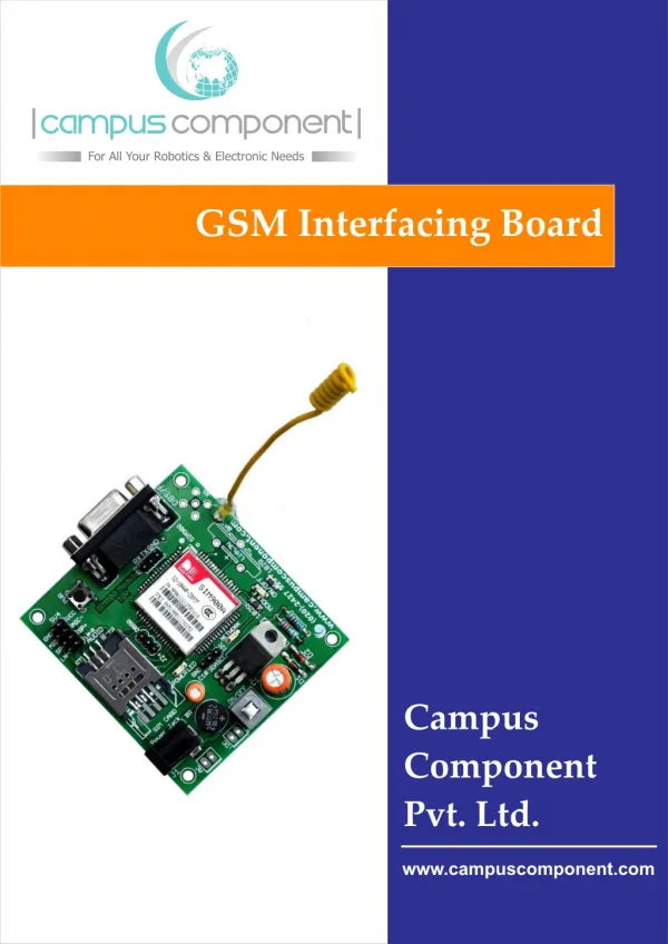
GSM Interfacing Board Campus Component Pvt. Ltd. www.campuscomponent.com
GSM Interfacing Board DISCLAIMER Information furnished is believed to be accurate and reliable at the time of publication. However, Campus Component Pvt. Ltd. assumes no responsibility arising from the use of the specifications described. The applications mentioned herein are used solely for the purpose of illustration and Campus component Pvt. Ltd. makes no warranty or representation that such applications will be suitable without further modification, nor recommends the use of its products for application that may present a risk to human life due to malfunction or otherwise. Campus Component Pvt. Ltd. does not assume any liability arising out of the application or use of any product or circuit described herein; neither does it convey any license under its patents rights, nor the rights of other. Campus Component Pvt. Ltd. reserves the right to alter its products without prior notification. For the most up-to-date information, please visit our web site at Pictures are representational only and actual product may vary. http://www.campuscomponent.com Copyright © 2011 CAMPUS COMPONENT Pvt. Ltd. All rights reserved. Campus Component Pvt. Ltd.®, logo and combinations thereof, are registered trademarks of CAMPUS COMPONENT Pvt. Ltd. Other terms and product names may be trademarks of others. www.campuscomponent.com
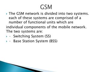
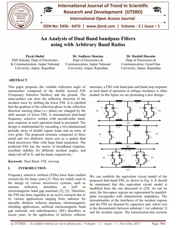
GSM Interfacing Board GSM Interfacing Board Introduction: GSM (Global System for Mobile) / GPRS (General Packet Radio Service) TTL -Modem is SIM900ADual-band GSM / GPRS device, works on frequencies 900 MHZ and 1800 MHZ. It is very compact in size and easy to use as plug in GSM Modem. The Modem is designed with 3V3 and 5V DC TTL interfacing circuitry, which allows User to directly interfacewith5V Microcontrollers (PIC, AVR, Arduino, 8051 etc.)as well as 3V3 Microcontrollers (ARM, ARM Cortex XX, etc.). The baud rate can be configurable from 9600-115200 bps through AT (Attention) commands. This GSM/GPRS TTL Modem has internal TCP/IP stack to enable User to connect with internet through GPRS feature. It is suitable for SMS as well as DATA transfer application in mobile phone to mobile phone interface. The modem can be interfaced with a Microcontroller using USART (Universal Synchronous Asynchronous Receiver and Transmitter) feature (serial communication). Features: · Dual Band GSM/GPRS : 900 / 1800MHz · Built in RS232 to TTL and viceversa Logic Converter (MAX232) · Configurable Baud Rate · SMA (SubMiniature version A) connector with GSM L Type Antenna ·Built in SIM (Subscriber Identity Module) Card holder · Built in Network Status LED Inbuilt Powerful TCP / IP (Transfer Control Protocol / Internet Protocol) stack for internet data transfer through GPRS (General Packet Radio Service) Audio Interface Connectors (Audio in and Audio out) Most Status and Controlling pins are available Normal Operation Temperature : -20 °C to +55 °C Input Voltage : 5V to 12V DC DB9 connector (Serial Port) provided for easy interfacing · · · · · · www.campuscomponent.com
GSM Interfacing Board Hardware Description: DB9 Connector (Serial Port) GSM ON Switch GND RXD TXD GND and VCC Microphone MIC+ and MIC- Speaker SP- and SP+ Line in LN-L and LN-R Antenna Antenna GSM SIM900 Module SIM Card Holder GSM Enable Status LED Network LED Power LED AC/DC Input Socket LM317 Voltage Regulator Bridge Rectifier On/Off Switch SIMCom SIM900A GSM Module: This is actual SIM900 GSM module which is manufactured by SIMCom. Designed for global market, SIM900 is a quad-band GSM/GPRS engine that works on frequencies GSM 850MHz, EGSM 900MHz, DCS 1800MHz and PCS 1900MHz. SIM900 features GPRS multi- slot class 10/ class 8 (optional) and supports the GPRS coding schemes CS-1, CS-2, CS-3 and CS-4. With a tiny configuration of 24mm x 24mm x 3mm, SIM900 can meet almost all the space requirements in User’s applications, such as M2M, smart phone, PDA and other mobile devices. MAX232 IC: The MAX232 is an integrated circuit that converts signals from an RS-232 serial port to signals suitable for use in TTL compatible digital logic circuits, so that devices works on TTL logic can share the data with devices connected through Serial port (DB9 Connector). Serial port / DB9 connector: User just needs to attach RS232 cable here so that it can be connected to devices which has Serial port / DB9 Connector. www.campuscomponent.com
GSM Interfacing Board Power Supply Socket: This power supply socket which actually named as AC/DC Socket provides the functionality to user to connect external power supply from Transformer, Battery or Adapter through DC jack. User can provide maximum of 12V AC/DC power supply through AC/DC socket. This is power supply designed into maximum protection consideration so that it can even prevent reverse polarity DC power supply as well as DC conversion from AC power Supply. It also includes LM317 Voltage Regulator which provides an output voltage adjustable over a1.2V to 37V. Power On/Off and GSM On Switch: Power On/Off switch is type of push-on push-off DPDT switch which is used for only make power supply on/off provided through AC/DC Socket indicated by ‘Power LED’. GSM On Switch is type of Push on DPST tactile switch which is used for only to make GSM module ‘On’ indicated by ‘Module On/Off LED’ while initiating with Network indicated by ‘Network Indication LED’. SIM (Subscriber Identity Module) Card Slot: This onboard SIM card slot provide User functionality of insert a SIM (GSM only) card of any service provider. Process of inserting and locking SIM card into SIM card slot is given in this manual. While inserting in and removing out SIM card from SIM card slot, User needs to take precaution that power supply should be OFF so that after making Power supply ON it will be easy to reinitialize with SIM for this module. Indicator LEDs: Indicator LEDs just used to indicate status accordingly. These are three LEDs represents Power On/Off Status, Network Status and Module On/Off Status respectively. Power LED will keep on until the power supply is enable to this board by using push-on push-off switch. Network Status LED will show whether inserted SIM card successfully connected to service provider’s Network or not, in short signal strength. Module On/Off indicator LED will show status of GSM module’s power on/off. www.campuscomponent.com
GSM Interfacing Board RXD, TXD and GND pins (JP2): These pins are used to connect devices which needs to be connected to GSM module through USART (Universal Synchronous Asynchronous Receiver and Transmitter) communication. Devices may be like Desktop or Laptop Computer System, Microcontrollers, etc. RXD (Receive Data) should be connected to TXD (Transmit Data) of other device and viceversa, whereas GND (Ground) should be connected to other device’s GND pin to make ground common for both systems. GND RXD TXD GND RXD TXD GSM Module Device Audio Connectors: Audio Connectors deals with Audio related operations. These pins already shown in hardware description diagram. These are eight pins in a group of two each denoted by SV4. GND (0V Supply) and VCC (+5V Supply) are used to have source for external device. MIC+ and MIC- used to connect Microphone (abbr. as Mic) through which user can give audio input while calling. SP- and SP+ used to connect Speaker (can be connected to amplifier circuit if necessary) through which User can hear audio output. LN-L and LN-R used to connect Line in to GSM module. Debugger (DBG-R and DBG-T) Connectors (J2): These connectors are 2-wire null modem interface DBG_TXD and DBG_RXD. These pins can be used for debugging and upgrading firmware. User generally no need to deal with these pins. www.campuscomponent.com
GSM Interfacing Board Inserting SIM card into SIM card Slot/Holder: Here is the process how to insert SIM card into SIM card slot. User just need to unlock SIM card cover by sliding back. Then user need to open this cover and insert SIM card according to slot. Put down cover on SIM card and then lock by sliding forward. Warning: Be careful about SIM card slot as it is too delicate one while inserting in and removing out SIM card. Power On/Off and Module On/Off process: Here is the process how User should make power supply on/off and module on/off. First of all User need to connect external power supply by using Battery / Adapter / Transformer. Now User needs to press Power On/Off switch (It is push-on push-off switch, thus User need to push it to make power on and push it again to make power supply off). Two LEDs will glow, one is Power On/Off indicator LED and another one is Network Status LED (which glows continuous to indicate no network or searching for network). After this User needs to press Module on switch (denoted as PWR) for at least 2 seconds. As soon as Module On/Off LED will glow User can release this switch, Network LED will blink to indicate signal strength. Note: If message sending, receiving, calling functions are failed due to weak signal strength then User needs to check SIM card’s service provider’s availability in coverage area, its not mean that GSM Module is not working properly. Connecting GSM module with RS232 (SB9-DB9) Serial Cable: User can connect GSM interfacing board either through Serial port or through Serial to USB converter. Here is process to connect RS232 cable to GSM interfacing board. www.campuscomponent.com
GSM Interfacing Board Connecting GSM Module with Serial to USB converter through RXD, TXD and GND: This module is designed in a way so that User can connect this module without Serial cable, this module can be connected to any of Serial to USB converter module or cable. Here we have shown demo how to connect this interfacing board with CP2102 Serial to USB converter Module through RXD, TXD and GND. Connect CP2102 Serial to USB converter module to PC through USB cable, connect one end of USB cable to PC’s USB connector and connect another end of USB to CP2102 module’s USB connector. Connect three Single Berg Wires to CP2102 modules’s RXD, TXD and GND pin. Then connect RXD wire to TXD of GSM module and TXD wire to RXD of GSM module. Make GND common by connecting GND wire to GND pin of GSM module. Testing GSM Module on Terminal Software: Terminal software used share the data through Serial port. Hence here also User need this software to test GSM module. For demo purpose we are going to show demo for how to send SMS and how to dial a call through ‘Realterm’ software. First of all install Realterm, it will create its own shortcut on Desktop. Then double click on Realterm icon. www.campuscomponent.com
GSM Interfacing Board Window will appear. Select Baud Rate as ‘9600’. www.campuscomponent.com
GSM Interfacing Board Select COM port through which GSM module is connected. (This can be known from ‘Camputer Management > Device Manager’) Click on ‘Open’ to open the port or to start communication. Click on Change button. www.campuscomponent.com
GSM Interfacing Board To initialize GSM module type ‘AT’ in capital letters and then press enter key on keyboard. If there are no errors occur in this communication then it will send ‘OK’. To send SMS type following commands AT+CMGF=1, press enter key, It will return ‘OK’ then proceed, AT+CMGS=“9876543210” <user can put any 10 digit number> type message after getting letter ‘>’ after end of SMS press Ctrl+z on keyboard If it returns ‘+CMGS: 203’ (or any other number)‘OK’ then SMS sent successfully. www.campuscomponent.com
GSM Interfacing Board To dial a call type following commands ATD+919876543210; <user can provide any 10 digit number with country code> it will return ‘OK’ if there are no errors occurs in communication to disconnect type ATH if it returns ‘OK’ it means call disconnected successfully. www.campuscomponent.com
GSM Interfacing Board Contact Us Campus Component Pvt. Ltd. Ackruti Chambers, Office No. 308, 3rd Floor, Near Laxminarayan Theater, Swargate, Pune- 411037 Mobile : +91 9767444555 Landline : +91 20 24275291 e-mail Address: sales@campuscomponent.com www.campuscomponent.com