Download
1 / 50
550 likes | 2.32k Views
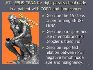
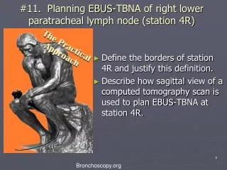
#11. Planning EBUS-TBNA of right lower paratracheal lymph node (station 4R). Define the borders of station 4R and justify this definition. Describe how sagittal view of a computed tomography scan is used to plan EBUS-TBNA at station 4R. 1. Bronchoscopy.org.

E N D
#11. Planning EBUS-TBNA of right lower paratracheal lymph node (station 4R) • Define the borders of station 4R and justify this definition. • Describe how sagittal view of a computed tomography scan is used to plan EBUS-TBNA at station 4R. 1 Bronchoscopy.org
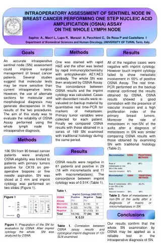
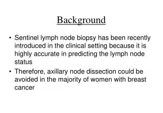
Case description(practical approach # 11) • A 77 year-man with a 50 pack –year history of smoking presents with abnormal CXR performed preoperatively for hernia repair. • Computed tomography shows a 1.5 X 1 cm right upper lobe nodule and a 1.4 cm right lower paratracheal lymph node. • Patient is referred for tissue diagnosis Bronchoscopy.org 2
Case description(practical approach #11) Axial, coronal and sagittal CT views from the patient Coronal CT view Axial CT view 4R Sagittal view 4R 4R Bronchoscopy.org 3
Initial Evaluation Procedural Strategies Techniques and Results Long term Management The Practical Approach • Examination and, functional status • Significant comorbidities • Support system • Patient preferences and expectations • Indications, contraindications, and results • Team experience • Risk-benefits analysis and therapeutic alternatives • Informed Consent • Anesthesia and peri-operative care • Techniques and instrumentation • Anatomic dangers and other risks • Results and procedure-related complications • Outcome assessment • Follow-up tests and procedures • Referrals • Quality improvement Bronchoscopy.org 4
Initial Evaluations • Exam • Decreased air entry bilaterally and prolonged exhalation • Functional status ECOG 3 • Comorbidities • COPD ( FEV1 23% predicted) • Coronary artery disease • Support system • Lives at home by himself • Patient preferences • Desires diagnosis and considers all available active treatment options. Bronchoscopy.org 5
Procedural Strategies *Ann Thorac Surg 2007;84:177-181 **J Thorac Cardiovasc Surg 2006;131:822-829 *** Eur J Cardiothorac Surg. 2007 Jul;32(1):1-8 • Indications • Invasive lymph node staging? • Invasive staging should be performed in patients with 1 or more risk factors for occult N2 disease* ** *** • The patient in this case has clinically evident N2 disease (1.4 cm right paratracheal node) • Bronchoscopic inspection can be performed at the time of EBUS-TBNA. • Diagnosis and staging can be performed during a single procedure. Bronchoscopy.org 6
Procedural Strategies • Indications • Sample 4R (right paratracheal node) for diagnosis and staging • Mediastinal lymph node involvement is found in 26% of newly diagnosed lung cancer patients* • The presence of lymph node metastasis remains one of the most adverse factors for prognosis in NSCLC • 4R nodal involvement in this patient suggests stage IIIA • inoperability and/or • need for treatment by chemotherapy and/or radiotherapy • * Spira A, Ettinger DS. Multidisciplinary management of lung cancer. N Engl J Med 2004; 350: 379–392. 7 Bronchoscopy.org
Procedural Strategies ***Herth F et al. Thorax 2006;61;795-798 *Chest 2004; 125:322–325 **Eur Respir J 2009; 33: 1156–1164 • Contraindications: • None • Expected Results: • The diagnostic rate of EBUS-TBNA for station 4R is: • 71-94 % * *** • Experienced team and operator • Risks-benefits: • No serious complications reported in the literature. • Agitation, cough, and presence of blood at puncture site reported infrequently.** • Benefits: • accurate, safe and same day procedure • diagnosis and staging at the same time Bronchoscopy.org 8
For station 4R, EBUS-TBNA has slightly better yield than conventional TBNA Chest 2004; 125:322–325 Bronchoscopy.org
The yield of EBUS-TBNA for diagnosing malignancy in station 4R is as high as 94% Bronchoscopy.org Herth F et al. Thorax 2006;61;795-798
Procedural Strategies *Chest. 2003; 123: 157-66 **Lung Cancer. 2003; 41: 259-67 ***Chest 2007;132;202-220 • Diagnostic alternatives: • CT-guided percutaneous needle aspiration of mass; high diagnostic rate (91%) but does not provide staging, and has increased risk for pneumothorax (5-60%)* • EUS-FNA (esophageal ultrasound) may reach 4R node; Sensitivity 81-97% Specificity 83-100% ** • Mediastinoscopy: considered gold standard. • Bronchoscopic airway inspection would still be required • More invasive • VATS: most invasive of alternatives. • Only provides access to ipsilateral nodes. 75% sensitivity***. • Benefits include definitive lobar resection at same time if node negative. 11
For station 4R, EBUS-TBNA is superior to EUS-FNA Am J Respir Crit Care Med Vol 171. pp 1164-1167, 2005 Bronchoscopy.org
Procedural Strategies Risks-Benefits Cost effectiveness- no formal evaluations have been published In 2 separate decision-analytic models, both (EUS-FNA + EBUS-FNA) and (conventional TBNA + EBUS-FNA) were more cost-effective approaches than Mediastinoscopy for staging patients with NSCLC and abnormal mediastinal lymph nodes on non-invasive imaging* ** A strategy adding EUS-FNA to a conventional lung ca staging approach (mediastinoscopy thoracotomy) reduced costs by 40% per patient*** May actually increase health care costs if done in low volume centers by less experienced operators**** ***** Start up costs Cost of equipment ~100K******and training Physician reimbursement ~$280; facility reimbursement $257****** *Gastrointestinal Endoscopy 69, No. 2, Supp 1, 2009, S260 **J Bronchol 2008;15:17–20 ***Thorax 2004;59;596-601 ****Lung Cancer 64 (2009) 127–128 *****J Bronchol 2008; 15:127-128 ****** Southern Medical Journal 2008;101,No5;534-38 Bronchoscopy.org
Procedural Strategies Drawing modified from Herth F et al. J Bronchol Volume 13, Number 2, 2006 • Informed consent for EBUS-TBNA was obtained: • There were no barriers to learning identified. Patient has good insight into his disease and realistic expectations. BI #. Practical Approach Title 14
Procedural techniques and resultsAnesthesia and perioperative care Conscious (moderate) sedation May be performed in bronchoscopy suite Cost savings compared to general anesthesia. Visualization and biopsy of smaller nodes technically more difficult than with general anesthesia. General anesthesia with LMA (#4 or 4.5 ) Better visualization of higher nodes (station 1 and 2) compared with ET tube May be performed in bronchoscopy suite May not be appropriate in severe obesity or severe untreated GERD General anesthesia with ET tube (#8.5 for female and #9 for male patients) Usually performed in OR . EBUS scope directed more centrally in airway which may make biopsies more difficult J Cardiothorac Vasc Anesth 2007; 21:892–896 15 Bronchoscopy.org Chest 2008;134;1350-1351
Procedural Techniques and Results • Instrumentation • EBUS scope- direct real time US imaging with curved array ultrasound transducer incorporated in distal end of bronchoscope • Ultrasound processor • Adjustable gain and depth • B mode and Doppler capabilities • Needle • 22 gauge acrogenic needle with stylet • Needle guide system locks to scope • Lockable needle and sheath • Precise needle projection up to 4 cm Bronchoscopy.org 16
Procedural Techniques and Results • Anatomic dangers and other risks • Major blood vessels- pulmonary artery, azygos vein, superior vena cava and ascending aorta • Risk of canulating major vessel may be reduced with real time B mode and Doppler mode imaging • “Minor” oozing of blood at puncture site was reported in 1 study there have been no reports of major bleeding* • Pneumothorax and pneumomediastinum** • Have been reported with conventional TBNA but no reports in literature with EBUS guided FNA. Bronchoscopy.org 17 Chest 2004;126;122-128 **Eur Respir J 2002; 19:356–373
Procedural Techniques and Results • Number of aspirates* if ROSE not utilized • Best yield with 3 aspirates per station (see table) • Two aspirations per LN station are acceptable when at least one tissue core specimen is obtained. • Sensitivity 91.7%, NPV 96.0%, and accuracy 97.2% 18 Bronchoscopy.org * Chest 2008;134;368-374;
Procedural Techniques and Results • Results and procedure-related complications • EBUS-TBNA was performed under general anesthesia using a 9.0 endotracheal tube. • 4R nodal cytology diagnostic for non small cell carcinoma (adenocarcinoma). • Bronchoscopic inspection: normal airways • Transient laryngospasm post-extubation was relieved by positive pressure mask ventilation. Bronchoscopy.org 19
Long-term Management Plan • Outcome assessment • Patient was referred for multidisciplinary evaluation to include cardiothoracic surgery, oncology, and radiation oncology for potential trial enrollment for neoadjuvant treatment of stage IIIA adenocarcinoma of the lung.* • 5 year survival for IIIA non-small cell lung ca is 23%. • Follow-up tests and procedures • Patient will follow up in 2 weeks to ensure involvement of above specialties. • Referrals • See above. • Quality improvement • Diagnosis and N2 metastasis identified by single procedure. *Chest 2007;132;243S-265S Bronchoscopy.org 20
Q 1: Define the borders of station 4R and justify this definition. Bronchoscopy.org
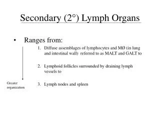
Station 4R (right lower paratracheal) based on IASLC map • 4R station includes: right paratracheal nodes, and pretracheal nodes extending to the left lateral border of trachea Left lateral border (J Thorac Oncol. 2009;4: 568–577)
Station 4R (right lower paratracheal) based on IASLC map • Upper border: intersection of caudal margin of innominate vein with the trachea. • Lower border: lower border of azygos vein. (J Thorac Oncol. 2009;4: 568–577) Bronchoscopy.org
Station 4R (right lower paratracheal) based on IASLC map Mountain-Dressler map (J Thorac Oncol. 2009;4: 568–577) Advantages of IASLC map Concise and anatomically distinct descriptions are provided in the IASLC map for the upper and lower borders of lymph node stations The pleural reflection (red arrows) no longer serves as the border between nodal stations 4 and 10 as in Mountain- Dressler map Bronchoscopy.org
Station 4R (right lower paratracheal) based on IASLC map IASLC Map 4R This is why station 4R is redefined Because lymphatic drainage in the superior mediastinum predominantly occurs to the right paratracheal area and extends past the midline of the trachea… the boundary between the right- and left-sided stations 2 and 4 lymph nodes has been reset to the left lateral wall of the trachea. Bronchoscopy.org (J Thorac Oncol. 2009;4: 568–577)
Lymphatic drainage in the superior mediastinum predominantly occurs to the right and extends past the midline of the trachea Inferior mediastinal lymphatic drainage Superior mediastinal lymphatic drainage Bronchoscopy.org M. Riquet / Cancer/Radiothérapie 11 (2007) 4–10
Furthermore.... • The left paratracheal nodes are localized around the left laryngeal recurrent nerve and lie behind the nerve. • Therefore, the border should be moved to the left tracheal margin. Bronchoscopy.org Zielinski M and Rami-Porta R. Journal of Thoracic Oncology 2; January 2007: 3-6
The oncologic and surgical midline for station 4 (and 2) is now the left lateral border of trachea Left lateral border of the trachea Station 4R (J Thorac Oncol. 2009;4: 568–577) Bronchoscopy.org
Q 2: Describe how the sagittal view of a computed tomography scan can be used to help plan EBUS-TBNA at station 4R. Bronchoscopy.org
CT views http://en.wikipedia.org/wiki Bronchoscopy International 30
CT views: sagittal • A sagittal (known as median) plane is perpendicular to the ground, which separates left from right. The midsagittal plane is the specific sagittal plane that is exactly in the middle of the body. http://en.wikipedia.org/wiki Bronchoscopy International
Which CT view is most useful for planning EBUS-TBNA for station 4R? EBUS scanning plane 12 1 3 9 R L Drawing modified from Herth F et al. J Bronchol Volume 13, Number 2, 2006 L R Bronchoscopy from head of patient The scope is positioned just proximal to the main carina. Turn it to the 3-o’clock position, and check lymph node station 4 R for lymph nodes; very often, 4R is more anterior …so gradually rotate the scope counterclockwise towards 12 o’clock position during the inspection. Bronchoscopy.org
When 4R has a pretracheal component, the sagittal view is useful; The aorta is seen in this particular scanning plane 4R station includes right paratracheal nodes, and pretracheal nodes extending to the left lateral border of trachea Ascending aorta Lymph node Thus, when the scanning plane (dashed red line) is oriented anteriorly (12 o’clock position), the lymph node and ascending aorta will be visualized Bronchoscopy.org
Therefore, the sagittal CT view identifies the EBUS scanning plane cephalad LN Ao PA Drawing modified from Herth F et al. J Bronchol Volume 13, Number 2, 2006 caudal The ascending aorta is anterior to the node Bronchoscopy International 34
Simultaneous sagittal CT view and EBUS image at station 4R cephalad LN Ao PA caudal cephalad Aorta The EBUS image at station 4R shows this pattern when the scanning plane is anterior towards the ascending aorta ( Doppler mode on). Node Bronchoscopy.org
To understand the use of sagittal CT view one must understand the reference points on the EBUS image cephalad caudal caudal The EBUS image is projected on the monitor as if the scope is horizontal The green dot on the monitor represents the point where the needle exits the scope and corresponds to the superior (cephalad) aspect of the body This dot is by default towards the 1’o’clock position of the screen Bronchoscopy International 36
The sagittal CT view is displayed as if the scope is vertical cephalad cephalad LN LN Ao Ao PA PA Several adjustments can be made to the coronal CT image in order to bring the scope to a horizontal position and the green dot cephalad (towards the 1 o’clock position on the screen) to match the EBUS image… Bronchoscopy International 37
Step by step cephalad cephalad LN LN LN Ao Ao 1 PA PA 2 • Print out a single frame of the CT image. • Flip the image is over like a page. The CT image is now adjusted so that the cephalad part is to the right, similar to the EBUS screen. • Next, the image will be rotated clockwise in order to horizontalize • the scope and bring the green dot cephalad towards the 1 o’clock position. Bronchoscopy.org
Step by step cephalad cephalad cephalad LN LN LN LN LN Ao Ao Ao PA PA PA LN 3 Now, the scope is horizontalized. The green dot is towards the 1o’clock position and the cephalad section of the image is towards the right side, as it is displayed by default on the EBUS screen Bronchoscopy.org 3
The two images now correlate and show all structures in the same locations cephalad Node LN Ascending Aorta LN Ascending Aorta Characteristic image at 4R when the scanning plane is sagittal towards the aorta Bronchoscopy International 40
When 4R has a pretracheal component, the sagittal view is useful; the Superior Vena Cava is seen in this scanning plane 4R includes right paratracheal nodes, and pretracheal nodes extending to the left lateral border of trachea Superior Vena Cava Lymph node Thus, when the scanning plane (dashed red line) is oriented anteriorly and to the right (endoscopically at 1-2 o’clock), the lymph node and superior vena cava will be visualized. Bronchoscopy.org
The sagittal CT view identifies the EBUS scanning plane cephalad LN SVC PA Drawing modified from Herth F et al. J Bronchol Volume 13, Number 2, 2006 caudal The SVC is anterior to the node Bronchoscopy International 42
Simultaneous sagittal CT view and EBUS image at station 4R cephalad LN SVC PA caudal cephalad caudal The EBUS image at station 4R shows this pattern when the scanning plane is anterior towards the SVC ( Doppler mode off) Bronchoscopy.org
To understand the use of sagittal CT view one must understand the reference points on the EBUS image caudal cephalad The EBUS image is projected on the monitor as if the scope is horizontal The green dot on the monitor represents the point where the needle exits the scope and corresponds to the superior (cephalad) aspect of the body This dot is by default towards the 1’o’clock position of the screen Bronchoscopy International 44
The sagittal CT view is displayed as if the scope is vertical cephalad cephalad LN LN SVC SVC PA PA caudal caudal Several adjustments can be made to the coronal CT image in order to bring the scope to a horizontal position and the green dot cephalad (towards the 1 o’clock position on the screen) to match the EBUS image… Bronchoscopy International 45
LN cephalad cephalad LN LN SVC SVC PA PA 1 2 caudal caudal Print out a single frame of the CT image The CT image has to be adjusted so that the cephalad part is to the right, as it is projected on the EBUS screen. Therefore, the image is flipped over like a page 3. Then it is rotated clockwise in order to horizontalize the scope and bring the green dot cephalad towards the 1 o’clock position. Bronchoscopy.org
cephalad cephalad cephalad LN LN LN SVC SVC 3 PA PA PA 3 caudal caudal caudal 3 LN LN LN SVC Now, the scope is horizontalized, the green dot is towards the 1o’clock position and the cephalad section of the image is towards the right side, as it is displayed by default on the EBUS screen Bronchoscopy.org
The two images now correlate and show all structures in the same locations cephalad LN LN SVC PA caudal LN SVC Characteristic image at 4R when the scanning plane is sagittal towards the superior vena cava Bronchoscopy International 48
Bronchoscopy International: Practical Approach, an Electronic On-Line Multimedia Slide Presentation. http://www.Bronchoscopy.org/PracticalApproach/htm. Published 2009 (Please add “Date Accessed”). All efforts are made by Bronchoscopy International to maintain currency of online information. All published multimedia slide shows, streaming videos, and essays can be cited for reference as: Thank you Bronchoscopy.org 49
Prepared with the assistance of SeptimiuMurgu M.D., University of California, Irvine www.bronchoscopy.org Bronchoscopy.org 50