Download
1 / 29
290 likes | 513 Views
Senior Design Project: Siemens LP Flow Guide (SIE). Design Team Calvin Stewart Carl Stewart Huy Lam Kirtan Patel Jessica Hanson. PROJECT PURPOSE. Existence of a Need. A Diffuser is designed to minimize the pressure loss between the last row blades and the condenser.

E N D
Senior Design Project: Siemens LP Flow Guide (SIE) DesignTeam Calvin Stewart Carl Stewart Huy Lam Kirtan Patel Jessica Hanson
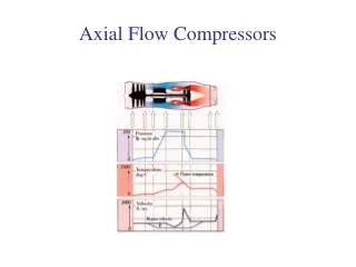
Existence of a Need A Diffuser is designed to minimize the pressure loss between the last row blades and the condenser. This flow guide is hard bolted onto the inner casing and can not alter its geometry to suit different operating conditions. To alleviate this problem a design is needed that can Modify the profile of the flow guide to optimize its performance at various back pressures.
Design Requirements Original Requirements • Simple Design • Able to increase and decrease the flow guide length, change profile, and Rfg • Continuous adjustment over a year span • Backup system to prevent shutdown of the steam turbine • Repeatedly attach to the same axial and transverse position
Design Requirements Modified Requirements • Only design top center section • Only a 2D design is required • Manufacturing process is not an issue • Cost is not an issue • FBD and Stress Calculations • Design for a safety factor of 2 • Use hydro-actuators with compressed water (steam).
2D Summer Working Model was used as design optimization tool The Blue Circle represents the geometry necessary during the summer for optimized efficiency
2D Winter Working Model was used to validate conformance to the shape change design requirements The Orange Circle represents the geometry necessary during the winter for optimized efficiency
2D Animated Demonstration of Conformance to Design Requirements
FBD • Factor of safety is 2. Therefore, the loads are doubled. • Assume massless rods/links. • Use 2- force members.
Stress • 3 Kilopascal Pressure • Conservative value • maximum pressure seen on outside diffuser surface area
Actuators • An Actuator is a mechanical device that can be use to move or control a mechanism or system. • Hydraulic actuator(6 per section) • Advantages/Disadvantages
Actuators Hydraulic rotary linear actuators use a pressurized, incompressible fluid and a patented method to convert rotary motion into linear extension. Three Manufacturers http://www.eckart-gmbh.dehttp://www.peninsularcylinders.com/http://www.parker.com
Materials Major Components • Carbon Steel Alloy • Siemens Proprietary Friction Reduction Layer (over Diffuser Plates) Fluoroelastomers are fluorinated synthetic polymers designed for harsh environments including aggressive chemical and high temperature applications. Fluoroelastomers can perform up to 450 F to 500 F. Fluoroelastomer are resistant to • oils • lubricants • fuels • high temperature steam
Pin Sub-Assembly Individual Designs Design optimization and safety
Pin Sub-Assembly Pin Parts • Male Holder • Female Holder • Rod • Bolts
Slider Sub-Assembly Individual Designs Design optimization and safety
Slider Sub-Assembly Slider Parts • Cover Holder • Base Holder • Inset Ball Bearings
Final Assembly • Image of Assembly • Video rotating around Assembly
Bill of Materials A Bill of material is a list of parts going from assembly to sub-assembly to individual parts. The type of BOM we will use is an indented one. With the finished product at the head.
Operation of Mechanism In order for the system to function according to the requirements (over a yearly cycle) its important to have a feedback control system which will automatically adjust the mechanism based on recordable stimuli Possible Sampling Sources • Cooling Water • Thermocouple • Back Pressure • Pressure couple Start FBC at Steady State Sample Activate Actuators
Advisors Jeffrey R. Cheski Steam Turbine Engineering P11A12, COE Manager (407) 736-4743 Matt Johnston Steam Turbine Engineering P11A13, Engineer Lewis Gray Steam Turbine Engineering P11A13, Fellow Engineer Contact Information Project Details Calvin M Stewart, Steam Turbine Engineering P11A12, COE Intern (407) 736-4289