Download
1 / 58
580 likes | 601 Views
Explore the ASDEX Upgrade Programme's efforts in solving immediate issues for ITER preparation, scenario development, and physics base for DEMO. Understand the operation of ASDEX Upgrade Tokamak and its heating systems. Discover how ASDEX Upgrade bridges the gap to ITER.

E N D
News from the ASDEX Upgrade Tokamak Programme Hartmut Zohm for the ASDEX Upgrade Team MPI für Plasmaphysik, EURATOM Association • Introduction: The ASDEX Upgrade programme • Scenario development with W-wall • Disruption mitigation and avoidance • Fast particle physics • Pedestal and ELM physics • Conclusions Talk given at PPPL, Princeton, USA, February 3rd, 2010
Introduction: The ASDEX Upgrade Programme
AUG Programme in Preparation of ITER and DEMO • Solving ‚immediate‘ questions aiding the design of details for ITER • guide ITER design in areas where input is still missing (ELMs, • NTMs, first wall materials…) Preparing ITER operation • develop operation scenarios that ensure baseline operation (Q = 10) • and make possible ‘advanced’ operation (Q > 10 or steady state) Developing and improving the physics base for DEMO • DEMO is a ‘point design’ – need first principles understanding • to build ‘numerical tokamak’ (strong interaction with theory) • Educating fusion plasma scientists • train and educate the generation that will run ITER
The ASDEX Upgrade Tokamak • 'Medium size' tokamak • major radius 1.65 m • minor radius 0.5 m • plasma current 1.4 MA • magnetic field 2 - 3 T • pulse length < 10 s • heating power 24 MW Comprehensive set of diagnostic developed over the last ~20 years Versatile heating and fuelling systems open up wide operational space
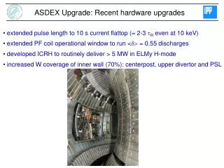
ASDEX Upgrade heating systems With the generator EZ4 back since mid-2009, we run high power discharges again Electron Cyclotron Resonance Heating: 2 MW @ 140 GHz 1(4) MW @ 140/105 GHz Neutral Beam Injection: 20 MW @ 70-100 kV NBCD by tang. beams Ion Cyclotron Resonance Heating: 8 MW @ 30-60 MHz
ASDEX Upgrade and JET form a step ladder to ITER ASDEX Upgrade JET ITER Geometry similar to ITER, linear dimensions scale 1:2:4
ASDEX Upgrade: operation with fully W-coated wall • Low Z-materials have too high erosion and T-retention for DEMO • demonstrate low retention with W-wall • demonstrate compatibility with high performance scenarios
ASDEX Upgrade: operation with fully W-coated wall # 22974 • At high gas puff (high density operation), Gin = Gout • retention dominated by ramp-up/down long pulse retention will be low
The basic problem: termination by W-accumulation Electron density [10 m ] 19 -3 edge center time central W concentration: ~ 5 x 10⁻⁴ (inacceptable!)
W concentration profile minor radius W content determined by sources and radial transport W peaking in the centre: neoclassical Inward pinch versus turbulent outward flux W influx across H-mode transport barrier: inward pinch versus ELM flushing W source profile (outside separatrix) net erosion versus retention
W sources and their impact on the W-concentration • Influx of eroded W (spectroscopy) • highest flux from divertor (ELMs) • W content in plasma dominated • by main chamber source • efficient divertor W-retention! • Flux from active ICRH antennae high • W sputtering from ICRH limiters • by sheath accelerated impurities • Low gas puff low ELM frequency • W concentration can run away!
Impurity scan gives stronger inward convection for higher charge Implication: W has strongest inward pinch – need ELM flushing Impurity transport in the pedestal is neoclassical
A simple model for W influx in H-mode plasmas • In between ELMs: • neoclassical transport in barrier • causes strong W density gradient • During ELM: • rapid decrease of W density due • to (prescribed) increase of D • low-Z impurities flushd from confined • region erode W at the limiters • a fraction of the eroded W returns • immediately (prompt redeposition) • Time dependent multi-species STRAHL calculation solves particle balance • using neoclassical D and vin plus an artificial ‚ELM‘ D of 20 m2/s
A simple model for W influx in H-mode plasmas • Scan of ELM frequency: • W influx increases • W edge density peaking decreases • Net effect is a reduction cW (temporal averages over ELM cycle, parameter variation: Te at the limiter, taken to match W influx measurements)
2.4T 2.55T z(m) 0.8 0.4 Prad #22957 0 2.0 Position of ECRH very sensitive and has to be within rtor~0.2 to suppress W-accumulation with ECRH w/o ECRH 4.0s 6.0s -0.4 1.5 MW/m3 -0.8 R(m) 1.0 1.2 1.6 2.0 2.4 0.5 0 0 0.2 0.4 0.6 0.8 1 rtor Central ECRH suppresses accumulation efficiently Radiation profile Sensitivity of localisation suggests that physics other than Dturb contributes Modelling indicates that a-heating might play this role in ITER (AUG) problem: density peaking leads to ECRH cut-off – need O2/X3-mode!
Tailoring of W content by Gas Puff • Lowering gas puff decreases ELM frequency, increases stored energy • W content also goes up – optimisation needed (no gas puff accumulation) • increasing PECRH or Ptot allows to further decrease gas puff
2008 >7 days after Bor. 0-7 days after Bor. Operational space of the all-W ASDEX Upgrade • Recipe for standard H-mode • need central ECRH to avoid • impurity accumulation • need ELM frequency > 70 Hz • to periodically flush edge • restrict divertor heat flux to • 10 MW/m2 to protect tiles • Impact on: • density range (finite gas puff, • ECRH cut-off) • q95 range (ECRH on-axis) • confinement (gas puff • deteriorates pedestal) • heating power (protect tiles) 1.2 1.1 1.0 Wmhd [MJ] 0.9 0.8 MoreECRH or boronise Ptot = 9-12 MW 0.7 1MA, d0.3 0.6 0 2 4 6 8 10 12 2002-2006, D,puff = 0
Extension of upper density limit: ECRH cut-off TORBEAM modelling Te,max = 2 keV; ne,max = 1.2·1020 1/m3 2.50 T 1.67 T Absorption along beam X2-Resonance serves as „beam-dump“ B=1.80 T 140GHz ECRH at schemes other than ‚classical‘ X2 have been explored: O2, X3 (cut-off densities: X2: 1.2 1020 m-3, X3: 1.6 1020 m-3, O2: 2.4 1020 m-3)
Extension to low q95: central X3-ECRH at lower Bt Stationary type I ELMy H-mode at 1.8 T / 1 MA → q95 = 3.3 n/nG = 0.7, bN = 1.7, H = 0.9 – target for optimisation of ITER scenario 2
Extension to higher heating power: impurity seeding • With reduction of C-content, divertor radiation strongly reduced • Impurity seeding applied to protect divertor in C-free environment • feedback controlled N2-seeding reliably protects tiles • sensor: thermocurrents between divertor plates ~ divertor heat flux
Impurity seeding allows to go to high P/R AUG ITER #25844 Scen. 2 P[MW] 20 120 P/R [MW/m] 12 19 H 1 1 bN 2.7 1.8 ne [1020 m-3] 1 1 n/nG 0.7 0.85 q95 3.9 3.1
Surprise: N2 seeding also improves confinement! With N2 seeding, energy confinement increases by 10-20% In addition, ELMs become smaller and more frequent (fELM 20-50%)
Extension to better confinement: N2 seeding • Improvement mainly from Ti, ne essentially unchanged (not an RI mode!) • Ti gradient at half radius steeper – dilution reduces ITG growth rate (GS2) • Ti pedestal extends to higher values – dilution plus different ELMs? • (cN 2-4 %, DZeff 0.5 - 1)
Extension to better confinement: N2 seeding • ELM energy loss drops (35 kJ → 20 kJ), shorter duration, less large filaments • not really consistent with increased pedestal temperature – role of SOL?
Ptot = 9-12 MW 1MA, d0.3 Extension to better confinement: N2 seeding • Performance improved back to • previous level with C-wall • even in unboronised machine • and with finite gas puff • improved H-mode continues • to be a robust option for • improved performance • Still to come now that EZ4 back • exploration of benefit of higher • triangularity (d < 0.35 so far) • zero gas puff with more PECRH? 2008 >7 days after Bor. 0-7 days after Bor. N2 seeded, Bor. N2 seeded no Bor. (2009)
Modelling for ITER Q=10 scenario W accumulation only for very low values of Dturb!
Avoidance of density limit disruption by ECRH @ q=2 • Target: ohmic density limit discharge, high q95 = 6.5 • MARFE formation triggers (3,1) and then (2,1) mode which disrupts plasma (collaboration CNR Milano /ENEA Frascati)
Avoidance of density limit disruption by ECRH @ q=2 • Injecting ECRH (PECRH = 0.6 MW ~ POHM) significantly delays (2,1) onset • in this period, the density continues to increase (formally above nGW!) • not just a power balance effect – need to localise ECRH @ q=2!
Avoidance of density limit disruption by ECRH @ q=2 • Turning off gas valve after ECRH onset allow to recover discharge • algorithm presently triggered by loop voltage increase (MARFE occurrence) • may be a route to operate close to nGW much safer than without
Disruption avoidance by ECRH – high b case • Chose a more ambitious target: q95 = 3.9, bN=2.6 with early (2,1) NTM
Disruption avoidance by ECRH – high b case • 1.5 MW of ECCD sufficient to avoid disruption, prepare safe landing • note: discharge never recovers performance – need to develop strategy • analysis of ‘scalability’ ongoing’
Disruption mitigation by high pressure gas jet • ASDEX Upgrade routinely uses disruption mitigation • massive Ne puff from high pressure valve, triggered by locked mode • on ASDEX Upgrade, main aim is to reduce halo current forces • Additional research for ITER • mitigate power load by radiation • substantially increase density • to avoid generation of runaways • Need two orders of magnitude • problem of fuelling efficiency ‘Slow’ valves 15 bar, 2 x 32 cm3 ‘Fast’ valve 60 bar, 80 cm3
Disruption mitigation by Injection of Gas Jet • valve open within 1 ms • flight time ~ 0.1 ms • density rise and plasma cooling by radiation edge -> center • cooling of q=2 surface triggers thermal quench • m =1 structure of SXR profile at thermal quench • reduced spike or roll-over of plasma current starts current quench • substantial reduction of forces • and thermal loads demonstrated!
thermal quench in-vessel valve AXUV vertical cameras = 180o Radiation in mitigated disruptions is asymmetric Toroidal asymmetry in total radiated power can even reverse • propagation of radiating zone, but no symmetrisation
Radiation in mitigated disruptions is asymmetric Radiation pattern has a ‘MARFE’ like structure during the energy quench • no ‘mixing’ in this phase, radiation mainly outside q=2 • later in the current quench, mixing occurs, but distribution of radiation • still not homogenous
Radiation in mitigated disruptions is asymmetric He I line (He killer gas) Radiation pattern has a ‘MARFE’ like structure during the energy quench • no ‘mixing’ in this phase, radiation mainly outside q=2 • later in the current quench, mixing occurs, but distribution of radiation • still not homogenous
neff / nc neff [m-3] E [V/m] (1.2 L dIp/dt) Substantial density increase towards nc • toroidal E field and hence nc tends to asymptotic value • neff /nc ~ 24 % with Ne and Eth < 0.45 MJ, but degrades with higher Wplasma • next: use more valves (linear superposition?)
Fast ion physics on ASDEX Upgrade • Aim is to obtain first principles understanding towards ITER • Needs strong collaboration with theory (available in-house ) • On the experimental side, we have to • characterise fast particle driven MHD and analyse its interaction • with the fast ions – comprehensive diagnostics available • (Mirnov, SXR, ECE-Imaging, Fast Ion Loss Detector) • characterise the fast particle distribution – just starting (CTS, FIDA)
Collective Thomson Scattering CTS Scattering geometry gyrotron: blue, receiver: green Fast ion velocity distribution • Collective Thomson Scattering (Risø effort) now starting to produce results • first measurements of the distribution function during NBI successful • progress hampered by problems with gyrotron (needs 105 GHz)
Radial structure of a single TAE • ICRH beatwave from two ICRH antennae with slightly different frequency • beatwave frequency is swept ‚adiabatically‘ in the range 150-200 kHz • ICRH power level below that usually needed to excite TAEs • at df = 177 kHz, a mode is excited (corresponding to 155 kHz in rest frame)
Radial structure of a single TAE • Comparison of radial eigenfunctions • allows to identify correct mode • pronounced minimum corresponds • to ‚odd‘ mode at 147 kHz • Note: this clearly shows TAEs can be • excited by ICRH beatwaves below • power level for fast particle excitation
The ‘Alfvénic Zoo’ • n = 3, 4,5 TAEs localised at r 0.5, up-chirping RSAEs at r 0.3
Fast particle losses due to a single TAE • Losses are in phase with mode • ‚convective‘ mechanism • note: ejected particles ≠ particles • that drive mode
Fast particle losses due to a single TAE • Above certain amplitude, incoherent • losses observed as well • reminiscent of ‚diffusive‘ mechanism • need more analysis…
Fast particle losses due to multiple AEs • In the phase with multiple TAEs and • Alfvén cascades, the level of • incoherent losses is high • note: different phase velocities, • need a ‚resonant‘ coupling