Download
1 / 56
610 likes | 639 Views
Prof. Christophe A. Serra Caine Rosenfeld, Florence Bally, Dambarudhar Parida, Dhiraj Garg. Intensification of NMP and ATRP (co)polymer syntheses by microreaction technologies. http://ics-cnrs.unistra.fr/caserra. Atelier de Prospective du GFP , Paris, Dec. 4 th , 2014. Outline. 1. Context

E N D
Prof. Christophe A. Serra Caine Rosenfeld, Florence Bally, Dambarudhar Parida, Dhiraj Garg Intensification of NMP and ATRP (co)polymer syntheses by microreaction technologies http://ics-cnrs.unistra.fr/caserra Atelier de Prospective du GFP, Paris, Dec. 4th, 2014
Outline • 1. Context • 2. Microprocessoverview • 3. Results • Synthesis of linear, block and branched (co)polymers • Influence of micromixing • Influence of microreactorgeometry • Influence of pressure • CFD Analysis • 4. Conclusion
Outline • 1. Context • 2. Microprocessoverview • 3. Results • Synthesis of linear, block and branched (co)polymers • Influence of micromixing • Influence of microreactorgeometry • Influence of pressure • CFD Analysis • 4. Conclusion
1. Context • Motivation • Synthesis of architecture-controlled (co)polymers • Block, linear or branched architectures • low PDI, defined MW • Applications in drug delivery, photoresist • Two-fold strategy • Chemistry • Rely on controlled/”Living” polymerization techniques • ATRP, NMP • Intrinsically “slow” reactions • Process • Development of an intensified and integrated continuous-flow microprocess
Outline • 1. Context • 2. Microprocessoverview • 3. Results • Synthesis of linear, block and branched (co)polymers • Influence of micromixing • Influence of microreactorgeometry • Influence of pressure • CFD Analysis • 4. Conclusion
2. Overview • Polymerization microprocess Synthesis (CMS) Monomer A Solvent Pump Initiator µreactor 1 Copolymer µmixer µreactor 2 Monomer B Pump Rosenfeld et al., React. Eng., 1 (5) (2007) 547-552; Bally et al., React. Eng., 5 (11-12) (2011) 542–547
2. Overview • Polymerization microprocess Synthesis (CMS) Monomer A Solvent Pump Initiator µreactor 1 Copolymer µmixer µreactor 2 Monomer B Pump Analysis (COA) Solvent Eluate Injection GPC Column Dilution Waste of detectors Train Rosenfeld et al., React. Eng., 1 (5) (2007) 547-552; Bally et al., React. Eng., 5 (11-12) (2011) 542–547
Recovery (IPR) 2. Overview • Polymerization microprocess Synthesis (CMS) Monomer A Solvent Pump Initiator nanoparticles solvent µreactor 1 µmixer µmixer Copolymer µmixer µreactor 2 Non solvent Monomer B Pump Analysis (COA) Solvent Eluate Injection GPC Column Dilution Waste of detectors Train Rosenfeld et al., React. Eng., 1 (5) (2007) 547-552; Bally et al., React. Eng., 5 (11-12) (2011) 542–547
2. Synthesis (CMS) • Continuous-microflow synthesis unit To COA
2. Synthesis (CMS) • Microreactors • Microtubular reactors (ID 876 µm) • Coiled tube (CT)
2. Synthesis (CMS) • Microreactors (cont’d) • Microtubular reactors (ID 876 µm) • Coiled tube (CT) • Coil flow inverter (CFI) • Better mixing • Lower RTD End of the helix After 1st bend Outlet After 2nd bend Inlet A.K. Saxena and K.D.P. Nigam, AIChE J., 1984, 30, 363-368
2. Microprocess features • Screening • Operating conditions • Flow rate, temperature, pressure, residence time, monomer concentration • Polymerization methods • FRP, CRP (NMP, ATRP, RAFT) • Rapid measurements • Analysis every 12 minutes • Libraries • Homopolymers • Copolymers
2. Microprocess features • Fully automated • Software controlled • Over night experiments • Pressure sensors • Temperature probes • Modular • New reaction blocks • New detectors • Raman • NIR • Inline polymer recovery • Colloidal suspension
Outline • 1. Context • 2. Microprocessoverview • 3. Results • Synthesis of linear, block and branched (co)polymers • Influence of micromixing • Influence of microreactorgeometry • Influence of pressure • CFD Analysis • 4. Conclusion
3. Copolymers (CMS) • Continuous one-step statistical copolymerization • Atom Transfer Radical Polymerization (ATRP) • Librairies of poly(DMAEMA-BzMA) / Influence of micromixer
3. Copolymers (CMS) • Continuous one-step statistical copolymerization • Continuous-flow setup 75°C
3. Copolymers (CMS) • Continuous one-step statistical copolymerization (cont’d) • Micromixers Parida et al., Green. Proc. Synt., 6 (1) (2012) 525-532
3. Copolymers (CMS) • Continuous one-step statistical copolymerization (cont’d) +35% Parida et al., Green. Proc. Synt., 6 (1) (2012) 525-532
3. Copolymers (CMS) • Continuous one-step statistical copolymerization (cont’d) +6,000 -50% Parida et al., Green. Proc. Synt., 6 (1) (2012) 525-532
3. Copolymers (CMS) • Continuous one-step statistical copolymerization (cont’d) X100 Parida et al., Green. Proc. Synt., 6 (1) (2012) 525-532
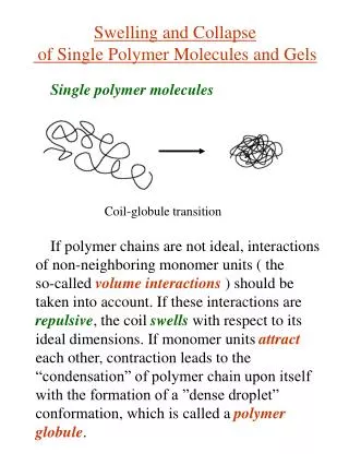
3. Copolymers (CMS) • Continuous two-step block copolymerization PBA-b-PS • Nitroxide-Mediated Polymerization (NMP) • PBA-b-PS with low polydispersity index (PDI) • Mixing between viscous and liquid fluids by means of microstructured mixers
Fluid B Fluid A Fluid B Fluid A Multilamination Multilamination 3. Copolymers (CMS) • Micromixers Fluid B Fluid A Mixing by … Bilamination ML20 ML50 CF ML45 Number of microchannels 1 16 15 10 Film thickness 450µm 45µm 20µm 50µm
3. Copolymers (CMS) • Sorting by form factor (F) • Multilamination • Bilamination
Fluid B Fluid A Fluid B Fluid A Multilamination Multilamination 3. Copolymers (CMS) • Micromixers Fluid B Fluid A Mixing by … Bilamination ML20 ML50 CF ML45 Number of microchannels 1 16 15 10 Film thickness 450µm 45µm 20µm 50µm F 2.8 3.9 4.6 1
3. Copolymers (CMS) • Continuous two-step block copolymerization(cont’d) • 1st block - 3:1 vol. BA/Toluene - "High" [AX]0 - 5% mol. free TIPNO • 2 equiv. Acetic anhydride Not purified Rosenfeld et al., Chem. Eng. Sci., 62 (2007) 5245-5250.
3. Copolymers (CMS) • Continuous two-step block copolymerization (cont’d) • Copolymer Not purified BR ML50 ML20 CF Rosenfeld et al., Chem. Eng. J., 15 (S1) (2008) S242-S246
2 Q2=9.3 µL/min 1.8 I p 1.6 1.4 1.2 0.5 1.5 2.5 3.5 4.5 5.5 Re' 3. Copolymers (CMS) • Continuous two-step block copolymerization (cont’d) • Influence of the micromixer geometry • Most efficient micromixer tested: wider and fewer microchannels Mainly controlled by the velocity CF ML45 PDI ML20 ML50 F Rosenfeld et al., Lab. Chip., 8 (2008) 1682-1687
Outline • 1. Context • 2. Microprocessoverview • 3. Results • Synthesis of linear, block and branched (co)polymers • Influence of micromixing • Influence of microreactorgeometry • Influence of pressure • CFD Analysis • 4. Conclusion
3. Microreactor geometry (CMS) • Recall one-step statistical copolymerization in CT Viscosity • Microreactor with internal mixing to overcome diffusion limitations
3. Microreactor geometry (CMS) • Linear polymers • Atom Transfer Radical Polymerization (ATRP) • Librairies of poly(DMAEMA) / CT vs. CFI
3. Microreactor geometry (CMS) • Linear polymers (cont’d) ID= 876 µm CT, 3 m CFI, 3 m • No significant increase in conversion between CT and CFI Parida et al., Macromolecules, 47 (10) (2014) 3282–3287.
3. Microreactor geometry (CMS) • Linear polymers (cont’d) ID= 876 µm CT, 3 m CFI, 3 m • Mn is higher in case of CFI (avg. +2000 g/mol) • Significant reduction in PDI for CFI (-0.13) Parida et al., Macromolecules, 47 (10) (2014) 3282–3287.
3. Microreactor geometry (CMS) • RTD measurements CFI CT • RTD is narrower in CFI compared to CT • High Pe in case of both reactors indicates low axial dispersion Parida et al., Macromolecules, 47 (10) (2014) 3282–3287.
3. Microreactor geometry (CMS) m m m • Branched polymers • Self-Condensing vinyl coPolymerization, adapted to ATRP b I a m m Inimer = Monomer + Initiator m m* b m b a m m* m m* a m 2-(2-bromoisobutyryloxy)ethyl methacrylate (BIEM) m* Matyjaszewskiet al., Macromolecules 1997, 30, 5192 a- b m
3. Microreactor geometry (CMS) • Branched polymers (cont’d)
3. Microreactor geometry (CMS) • Branched polymers (cont’d) • DMAEMA and BIEM conversions + 7.5% • Higher BIEM conversion for CFI Parida et al., Macromolecules, 47 (10) (2014) 3282–3287.
3. Microreactor geometry (CMS) • Branched polymers (cont’d) • GPC traces – Batch reactor • Presence of BIEM-initiated macromonomers/oligomers Parida et al., Macromolecules, 47 (10) (2014) 3282–3287.
3. Microreactor geometry (CMS) • Branched polymers (cont’d) • GPC traces (2 hrs) 10 % 5 % • Highest oligomeric units in batch • Lowest in CFI Parida et al., Macromolecules, 47 (10) (2014) 3282–3287.
3. Microreactor geometry (CMS) • Branched polymers (cont’d) • Polymer characteristics (BIEM 5mol% @ 2 hrs) +700 -0.28 • Mn exhibits the following trend: batch < CT < CFI • PDI follows the opposite trend: batch > CT > CFI Parida et al., Macromolecules, 47 (10) (20141)3282–3287
3. Microreactor geometry (CMS) • Branched polymers (cont’d) • Impact of flow inversion on molecular characteristics • Highest branching efficiency in CFI and lowest in batch • Controlled branched structure in microreactors especially in CFI Parida et al., Macromolecules, 47 (10) (20141)3282–3287
Outline • 1. Context • 2. Microprocessoverview • 3. Results • Synthesis of linear, block and branched (co)polymers • Influence of micromixing • Influence of microreactorgeometry • Influence of pressure • Scale-up • CFD Analysis • 4. Conclusion
3. Operating parameters (CMS) • Effect of pressure • Chemical system
3. Pressure (CMS) • Effect of pressure • Procedure
3. Pressure (CMS) • Effect of pressure (cont’d) • Polymer characteristics • Decrease in activation volume • Reduced termination • Increased density, thus increased residence time Parida et al., J. Flow Chem., 4 (2) (2014) 92-96.
3. Pressure (CMS) • Effect of pressure (cont’d) • Microreactor dimension 576 µm 876 µm 1753 µm Parida et al., J. Flow Chem., 4 (2) (2014) 92-96.
3. Pressure (CMS) • Effect of pressure (cont’d) • Microreactor dimension • Reduced diffusion distance Parida et al., J. Flow Chem., 4 (2) (2014) 92-96.
Outline • 1. Context • 2. Microprocessoverview • 3. Results • Synthesis of linear, block and branched (co)polymers • Influence of micromixing • Influence of microreactorgeometry • Influence of pressure • Scale-up • CFD Analysis • 4. Conclusion
Inlet Outlet
Inlet Outlet