Full Adder Display
Full Adder Display. Topics. A 1 bit adder with LED display Ripple Adder Signed/Unsigned Subtraction Hardware Implementation of 4-bit adder. Implementation of a Full Adder. (carry-in). Verilog Implementation. Use switches to input binary numbers—x, y, and z. z is the carry-in.


Full Adder Display
E N D
Presentation Transcript
Topics • A 1 bit adder with LED display • Ripple Adder • Signed/Unsigned Subtraction • Hardware Implementation of 4-bit adder
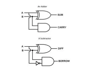
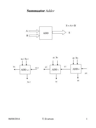
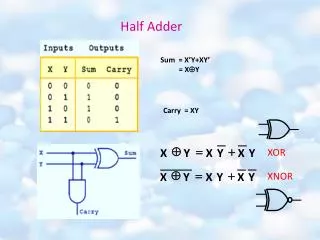
Implementation of a Full Adder (carry-in)
Verilog Implementation Use switches to input binary numbers—x, y, and z. z is the carry-in. Display the output on the LED. Press a button to determine which bit will be displayed. s represents the sum bit. c represents the carry-out bit. A mux is used to determine Whether s or c should be displayed.
Multiplexing 7-Segment Displays (Last Week) If s[1:0]=00, then x[3:0]. If s[1:0]=01, then x[7:4]. If s[1:0]=10, then x[11:8]. If s[1:0]=11, then x[15:12]. Use Quad 4-to-1 mux Get values for an[3:0] from btn[3:0] so that only one LED is displayed.
Explanation of the Code If btn[0] is pushed, t[0] is 0. If btn[1] is pusehd, t[0] is 1. So we can use t[0] as a selector bit for the MUX. t[ ] =s[] If the output of the MUX is a 0, a 0 Is displayed. If the output of the MUX is a 1, a 1 is displayed.
Implementation of a Full Adder (carry-in)
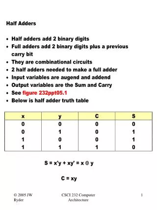
Four-Bit Adder C4 is calculated last because it takes C0 8 gates to reach C4. Each FA uses 2 XOR, 2 AND and 1 OR gate. A four-bit adder uses 8 XOR, 8 AND and 4 OR gate.
Hardware Simplification input carry ) 2 gate delays for C3!
Four-bit adder with Carry Lookahead Ripple adder uses 8 XOR, 8 AND and 4 OR gate. Lookahead implementation: 8 XOR, (4+6) AND, 1 2-input OR, 2 3-input OR.
Advantages • C1, C2 and C3 do not have to wait for C1 and C2 to progate. • C3 is propagated at the same time as C1 and C2.
Topics • Calculations Examples • Signed Binary Number • Unsigned Binary Number • Hardware Implementation • Overflow Condition
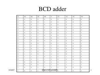
Unsigned Number (2-bit example)
Unsigned Addition • 1+2=
Unsigned Addition • 1+3= (Indicates Overflow) (Carry Out) Overflow can be an issue in unsigned addition.
Unsigned Subtraction (1) • 1-2= (1’s complement) (2’s complement)
Unsigned Subtraction (2) • 2-1= Discarded
Summary for Unsigned Addition/Subtraction • Overflow can be an issue in unsigned addition • Unsigned Subtraction (M-N) • If M≥N, and end carry will be produced. The end carry is discarded. • If M<N, • Take the 2’s complement of the sum • Place a negative sign in front
Signed Binary Numbers • 4-bit binary number • 1 bit is used as a signed bit • -8 to +7 • 2’s complement
Signed Addition (70+80) (Indicates a negative number) 70=21+22+26=2+4+64 80=24+26=16+64 10010110→01101001 →01101010 21+23+25+26=2+8+32+64=106 10010110↔-106 010010110 010010110↔ 21+22+24+27=2+4+16+128=150 Conclusion: There is a problem of overflow Fix: Use the end carry as the sign bit, and let b7 be the extra bit.
Signed Subtraction (70-80) (Indicates a negative number) 70=21+22+26=2+4+64 80=24+26=16+64=01010000→10101111→10110000 11110110→00001001 →00001010 21+23=10 11110110↔-10 (No Problem)
Signed Subtraction (-70-80) (Indicates a positive number! A negative number expected.) 70=21+22+26=2+4+64 80=24+26=16+64 101101010 →010010101 → 010010110 010010110 ↔21+22+24+27=2+4+16+128=150 101101010 ↔-150 Conclusion: There is a problem of overflow Fix: Use the end carry as the sign bit, and let b7 be the extra bit.
Observations • Given the similarity between addition and subtraction, same hardware can be used. • Overflow is an issue that needs to be addressed in the hardware implementation • A signed number is not processed any different from an unsigned number. The programmer must interpret the results of addition and subtraction appropriately.
The Mode Input (1) If M=0, = If M=1, = B0
The Mode Input (2) If M=0, If M=1,
M=0 (Addition) B3 B2 B0 B1 0
M=1 (Subtraction) 1 2’s complement is generated of B is generated!
Unsigned Addition When two unsigned numbers are added, an overflow is detected from the end carry.
Detect Overflow in Signed Addition Observe The caryinto the sign bit The carry out of the sign bit If they are not equal, they indicate an overflow.