Download
1 / 21
210 likes | 298 Views
Mineral grains from Ivuna (2004.06.16) Short summary. 4 samples removed from the Ivuna meteorite were imaged at beamline BL47XU of SPring-8 on June 16, 2004.

E N D
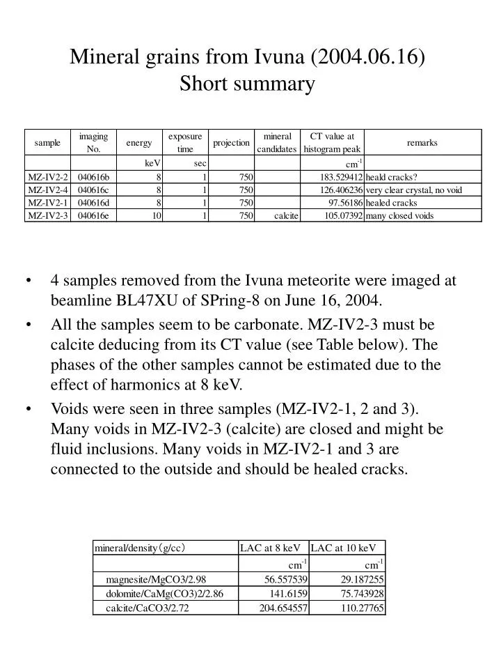
Mineral grains from Ivuna (2004.06.16)Short summary • 4 samples removed from the Ivuna meteorite were imaged at beamline BL47XU of SPring-8 on June 16, 2004. • All the samples seem to be carbonate. MZ-IV2-3 must be calcite deducing from its CT value (see Table below). The phases of the other samples cannot be estimated due to the effect of harmonics at 8 keV. • Voids were seen in three samples (MZ-IV2-1, 2 and 3). Many voids in MZ-IV2-3 (calcite) are closed and might be fluid inclusions. Many voids in MZ-IV2-1 and 3 are connected to the outside and should be healed cracks.
MZ-IV2-2 (040616b) cut/271.tif (width: 85.33 mm) Imaging No.: 040616b Sample: MZ-IV2-2; a piece of transparent crystal Beamline: BL20XU X-ray photon energy: 8 keV Exposure time for each projection: 1 sec. No. of pixels for each projection image: 512× 530pels No. of projection images for dark current :2 (1 each before and after sample imaging) No. of projection images for incident beam current (I0): 151 (+1; for determining the rotation axis) No. of projection images for transmitted beam current (I): 750 (+1; ditto) Imaging sequence: One I0 imaging after every 5 I imaging Pixel size of projection images: 0.23 micron Voxel size of reconstructed CT images: 0.23 micron No. of voxels: 512 × 512 × 530 Location of sample rotation axis:R0(z)= 0.007793×z +233.936012 ±0.828852(z=0~529) Byte images: PV=0: CT value = 0 1/cm PV=180: CT value = 183.529412 1/cm (peak value) Cut images: Threshold: PV=74 Erosion: 3 layers Dilation: 6 layers Voxel size: 0.23 micron Number of voxels: 371 × 331 × 509
MZ-IV2-2 (040616b): external shape -Z image +X image +X -Z +Y +Y +Y image -Z -Z +X +X +Y
MZ-IV2-2 (040616b): frequency diagram and phases CT value of calcite: 204.65 cm-1 Estimated LAC of calcite: 181.8 cm-1 CT value of dolomite: 141.62 cm-1 Estimated LAC of calcite: 125.1 cm-1 CT value = 0.88305(651) * LAC ? Minerals White (CTv >260 cm-1): ? Gray (CTv = 183.5 cm-1): calcite?? Black: void, air Identification of mineral phases from the CT values is difficult due to contribution of harmonics at this energy (8 keV). void carbonate cut/271.tif (width: 85.33 mm)
MZ-IV2-4 (040616c) cut/130.tif (width: 42.32 mm) Imaging No.: 040616c Sample: MZ-IV2-4; a piece of transparent crystal Beamline: BL20XU X-ray photon energy: 8 keV Exposure time for each projection: 1 sec. No. of pixels for each projection image: 512× 280pels No. of projection images for dark current :2 (1 each before and after sample imaging) No. of projection images for incident beam current (I0): 76 (+1; for determining the rotation axis) No. of projection images for transmitted beam current (I): 750 (+1; ditto) Imaging sequence: One I0 imaging after every 10 I imaging Pixel size of projection images: 0.23 micron Voxel size of reconstructed CT images: 0.23 micron No. of voxels: 512 × 512 × 280 Location of sample rotation axis:R0(z)= 0.007785×z +229.295481 ±0.000000(z=0~279) Byte images: PV=0: CT value = 0 1/cm PV=180: CT value = 126.406236 1/cm (peak value) Cut images: Threshold: PV=100 Erosion: 3 layers Dilation: 6 layers Voxel size: 0.23 micron Number of voxels: 184 × 405 × 280
MZ-IV2-4 (040616c): external shape -Z image +X image +X -Z +Y +Y +Y image -Z -Z +X +X +Y
MZ-IV2-4 (040616c): frequency diagram and phases CT value of calcite: 204.65 cm-1 Estimated LAC of calcite: 181.8 cm-1 CT value of dolomite: 141.62 cm-1 Estimated LAC of calcite: 125.1 cm-1 CT value = 0.88305(651) * LAC ? Minerals White (CTv >179 cm-1): ? Gray (CTv = 126.4 cm-1): dolomite-calcite?? Black: void, air Identification of mineral phases from the CT values is difficult due to contribution of harmonics at this energy (8 keV). carbonate cut/130.tif (width: 42.32 mm)
MZ-IV2-1 (040616d) cut/260.tif (width: 46.23 mm) Imaging No.: 040616d Sample: MZ-IV2-1; a piece of transparent crystal Beamline: BL20XU X-ray photon energy: 8 keV Exposure time for each projection: 1 sec. No. of pixels for each projection image: 512× 420pels No. of projection images for dark current :2 (1 each before and after sample imaging) No. of projection images for incident beam current (I0): 76 (+1; for determining the rotation axis) No. of projection images for transmitted beam current (I): 750 (+1; ditto) Imaging sequence: One I0 imaging after every 10 I imaging Pixel size of projection images: 0.23 micron Voxel size of reconstructed CT images: 0.23 micron No. of voxels: 512 × 512 × 420 Location of sample rotation axis:R0(z)= 0.008687×z +226.219933 ±0.643388(z=0~419) Byte images: PV=0: CT value = 0 1/cm PV=180: CT value = 97.561860 1/cm (peak value) Cut images: Threshold: PV=116 Erosion: 3 layers Dilation: 6 layers Voxel size: 0.23 micron Number of voxels: 201 × 340 × 400
MZ-IV2-1 (040616d): external shape -Z image +X image +X -Z +Y +Y +Y image -Z -Z +X +X +Y
MZ-IV2-1 (040616d): frequency diagram and phases CT value of calcite: 204.65 cm-1 Estimated LAC of calcite: 181.8 cm-1 CT value of dolomite: 141.62 cm-1 Estimated LAC of calcite: 125.1 cm-1 CT value = 0.88305(651) * LAC ? Minerals White (CTv >138 cm-1): ? Gray (CTv = 97.61 cm-1): magnesite-dolomite?? Black: void, air Identification of mineral phases from the CT values is difficult due to contribution of harmonics at this energy (8 keV). carbonate void cut/176.tif (width: 46.23 mm)
(1) Voids along healed cracks? We can see many voids. Some of them seem to be closed. But they are located along lines and seem to be healed cracks. MZ-IV2-1 (040616d): voids 255.tif 260.tif 250.tif 265.tif 270.tif 275.tif
MZ-IV2-3 (040616e) cut/418.tif (width: 115.46 mm) Imaging No.: 040616e Sample: MZ-IV2-3; a piece of transparent crystal Beamline: BL20XU X-ray photon energy: 10 keV Exposure time for each projection: 1 sec. No. of pixels for each projection image: 1024× 820pels No. of projection images for dark current :2 (1 each before and after sample imaging) No. of projection images for incident beam current (I0): 76 (+1; for determining the rotation axis) No. of projection images for transmitted beam current (I): 750 (+1; ditto) Imaging sequence: One I0 imaging after every 10 I imaging Pixel size of projection images: 0.23 micron Voxel size of reconstructed CT images: 0.23 micron No. of voxels: 1024 × 1024 × 820 Location of sample rotation axis:R0(z)= 0.006011×z +478.638705 ±0.872422(z=0~819) Byte images: PV=0: CT value = 0 1/cm PV=180: CT value = 105.073920 1/cm (peak value) Cut images: Threshold: PV=80 Erosion: 3 layers Dilation: 6 layers Voxel size: 0.23 micron Number of voxels: 502 × 199 × 820
MZ-IV2-3 (040616e): external shape -Z image +X image +X -Z +Y +Y -Z +Y image -Z +X +Y +X
MZ-IV2-3 (040616e): frequency diagram and phases CT value of calcite: 110.28 cm-1 Estimated LAC of calcite: 97.4 cm-1 CT value = 0.88305(651) * LAC Minerals White (CTv >149 cm-1): ? Gray (CTv = 105.1 cm-1): calcite Black: void, air ? calcite void cut/492.tif (width: 115.46 mm)
(1) Closed voids We can recognize many closed voids in slices of 95-104, 111-115, 127-144, 163?, 210-211, 269?, 314-317, 353, 382?, 411-424, 536-551, etc. MZ-IV2-3 (040616e): voids 100.tif 316.tif 418.tif (2) Voids along healed cracks? 572.tif
Glossary • Beamline Three beamlines (BL20B2, BL20XU and BL47XU) are now available at Spring-8 for X-ray microtomography. We can choose the beamline mainly depending on the sample size and the spatial resolution. • Browse image Some of a successive CT images of a sample can be seen at a glance by this image. Size scale (cm) and gray scale for CT values (cm-1) are shown in the right and left bottoms of the image, respectively. • Byte image An monochromatic image where the brightness of each pixel is expressed by 8 bit (0-255 steps). A series of byte images of an sample stored in the directory named “byte” are formed from original CT images by conversion from CT value to PV (usualy the theoretical LAC of a standard mineral is used for this conversion). • CT value This is the value of LAC in each pixel of an CT image. In other words, an CT image is expressed as spatial distribution of CT values. CT values are calculated by CT reconstruction. If we use a monochromatic X-ray beam, CT value is ideally equal to the LAC of a material. However, they are not identical with each other in practice. Their empirical relations were determined at BL20B2 and BL47XU of Spring-8 (see np.29 for the relation at BL47XU). From this relation, we can estimate materials from CT values. • Cut image This is a CT image, where unnecessary regions without sample are trimmed. A series of cut images of an sample stored in the directory named “cut” are formed from “byte” images by image processing using threshold for a sample and erosion and dilation procedures. • Imaging No. Imaging number shows the date of imaging and its order. For example, 031204c shows the third experiment (in alphabetical order) on 4 December, 2003. • LAC (Linear attenuation coefficient) (of X-ray) A characteristic properties for X-ray attenuation of a material. This is a function of the bulk density, the chemical composition and X-ray photon energy.. • Pixel One of many from which a 2-D image is composed. The shape is usually square. • Projection image CT images are reconstructed from a series of projection images by rotating a sample by180 degrees. The size of a projection image gives the size of a CT image. For example, projection images of 512 × 220pixels give 220 CT images of 512 × 512 pixels. • Projection image for dark current A projection image without X-ray beam (dark image). This gives back ground of the projection images. Usually, 1 (or 2) dark image(s) is (are) taken before and after sample imaging experiment and their average is used for CT reconstruction calculation. • Projection images for incident beam current (I0) A projection image of X-ray beam without sample (I0 image). This is taken at regular intervals of sample imaging (ussually 5 or 10 intervals).
Coordination system • Projection images for transmitted beam current (I) A projection image of sample (I image). The projection , p=ln(I0/I), is calculated and used for CT reconstruction. • Sample rotation axis The location of a sample rotation axis is required for CT reconstruction. This is called “center value”, which is generally described as a function of the height of a projection image (z: see the coordinate system). For example, the center value is expressed as follows: 249.934 -0.003046 × z ±0.320748(z = 0 - 219). • PV (Pixel value) This is the value that expresses the brightness of each pixel of a digital image. For example, the pixel is black and white for PV=0 and 255, respectively, in a byte image. • Voxel One of many from which a 3-D image is composed. The shape is usually cubic. (0,0,0) +X +Y +Z