Solar Energy Meter Lab
240 likes | 470 Views
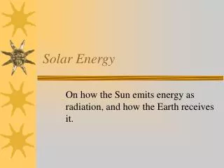
Solar Energy Meter Lab. Solar Energy Meter. On a bright, sunny day, solar energy strikes the earth at the rate of approximately 1000 Watts/m 2 – this is called the solar energy intensity. In lab today, you will build a solar energy meter to measure

Solar Energy Meter Lab
E N D
Presentation Transcript
Solar Energy Meter On a bright, sunny day, solar energy strikes the earth at the rate of approximately 1000 Watts/m2 – this is called the solar energy intensity. In lab today, you will build a solar energy meter to measure the energy intensity from the sun at the earth’s surface.
Solar Energy Meter Parts Here are the parts you will use: • +5 Volt modular power supply • DMM* • Breadboard * For a detailed explanation of the DMM, see the video from the Circuits Lab.
Solar Energy Meter “Circuit” This is the circuit you will build: • Breadboard • Switch Box • Light Sensor • TrimPot • Binary Voltmeter • LED Display (8-bits) • Wires for connecting components
Solar Energy Meter “Schematic” A “schematic” is a drawing of an electronic circuit made by an electrical engineer.
Components The parts (Components) you will use to build the Solar Energy Meter are: • Light Sensor Board • Senses the sun’s energy • Uses a Photodiode and an Op-Amp • Has an analog output voltage signal of 0 – 5 Volts • Binary Voltmeter Board • Changes the input voltage signal to binary “Bits” • LEDs • Display an 8-Bit binary number • Wires • Connect the parts together electrically
Task 1 – Check the Breadboard Setup Gnd Measure the Power Supply Voltage, V = ______ Volts +5V
TrimPot • Total resistance (Pin 1 to Pin 3) = 10 kOhms • Resistance at Pin 2 varies by turning the small adjustment screw (0 to +5V on Pin 2) • Use it to calibrate the Binary Voltmeter circuit • It is a variable resistor. Pins 1 2 3
8-Bit Binary Display • The LEDs at the output of the Binary Voltmeter are labeled from D7 to D0 • The LEDs have two digital states, on and off, representing the binary numbers “1” and “0” • D7 is the Most Significant Bit (MSB). D0 is the Least Significant Bit (LSB) • The 8-bit binary number can be converted to a decimal number using a formula MSB LSB
Why use Binary Numbers? • Binary numbers are used in almost all computers due to its use of digital electronic circuitry and logic gates. • Numbers are written in a combination of bits. • Counting in binary is straightforward. P. 13
How does counting in Binary work? • It works the same way that you have learned to count with Arabic numerals • Instead of 0-9, you now use only 0 & 1 • The pattern goes according to the following form:
8-bit Binary Numbers 00000101 = 5 For example, convert binary 0 0 0 0 0 1 0 1 into a decimal: MSB LSB …. + 0*23 + 1*22 + 0*21 + 1*20 = 5
Task 2 – Finish building the Calibration Circuit • Connect the Binary Voltmeter board to Gnd (orange wire) • Place the TrimPot as shown and: • Connect Pin 1 to Ground • Connect Pin 3 to +5 Volts • Connect Pin 2 to V Input on the Binary Voltmeter • Connect the LEDs • Connect the Red DMM wire to V Input +5V Gnd Short wire
Task 3 – How the Light Sensor Works • The Photodiode converts light photons to a current • The Amplifier converts the current to a voltage • The voltage output of the Light Sensor Board is proportional to the intensity of sunlight (Isolar, Watts / m2) Isolar Amplifier Photodiode V Output • The calibration equation for the Solar Light Meter is: • Isolar = 5.0 Ndecimal (Watts / m2)
Task 3 – Finish building the Solar Energy Meter • Remove the TrimPot and its wires • Plug in the Light Sensor Board (as shown) • Add an orange ground wire • Add a red wire from Vout to V Input
Task 4 – Use the Solar Energy Meter to measure the intensity of a light source • Place the spotlight in the ring stand so that the front of the bulb is 13 inches away from the top of the Light Sensor. • Make sure that the Photodiode is directly in the center of the beam. • Measure the Intensity of the light source at distances of 23, 19, 15, 11 and 7 inches.
Task 5 – Measure the Intensity of the Light Source at various distances Table B