Introduction to Computerized Engineering Graphics (ENGR 2220) - Dr. Omar E. Meza Castillo
ENGR 2220, taught by Dr. Omar E. Meza Castillo at the Inter American University of Puerto Rico, focuses on the fundamentals of engineering graphics. Students will learn key graphic terminology, spatial analysis, and solutions to engineering problems. The course covers object visibility, CAD software, and geometric representations in 2D and 3D. Prerequisite courses include Information and Computer Literacy and Fundamentals of Algebra. Assessment includes homework, quizzes, and exams.

Introduction to Computerized Engineering Graphics (ENGR 2220) - Dr. Omar E. Meza Castillo
E N D
Presentation Transcript
Computarized Engineering Graphics ENGR 2220 Professor: Dr. Omar E. Meza Castillo omeza@bayamon.inter.edu http://facultad.bayamon.inter.edu/omeza Department of Mechanical Engineering Inter American University of Puerto Rico Bayamon Campus
Syllabus • Catalog Description: Graphic terminology. Analysis and solutions of spatial problems. Symbols and standards as applied to engineering. Introduction to computer graphics: hardware and software. Mathematical elements in two or three dimensions for computer graphics. Object visibility. Use of programs for computer-aided design in engineering. • Prerequisites: GEIC 1000 – Information and Computer Literacy and GEMA 1200 – Fundamentals of Algebra . • Course Text: Bertoline, G R, Wiebe, E, Miller, C. Fundamentals of Graphics Communications. 5th, Mc Graw-Hill. 2006 .
Syllabus • Absences: On those days when you will be absent, find a friend or an acquaintance to take notes for you or visit the web page. Do not call or send an e-mail the instructor and ask what went on in class, and what the homework assignment is. • Homework assignments: Homework will be collected when due, with your name written legibly on the front of the title page. It is graded on a 0 to 100 points scale. Late homework (any reason) will not be accepted. • Quiz : There are several quizzes during the semester. • Partial Exams and Final Exam: There are three partial exams during the semester, and a final exam at the end of the semester.
Course Grading • The total course grade is comprised as follows: • Sketching Assignments 10% • Quiz 10% • Computer Projects 30% • Exam 1, Exam 2 and Exam 3 30% • Final Exam 20% • 100% • Cheating: You are allowed to cooperate on homework by sharing ideas and methods. Copying will not be tolerated. Submitted work copied from others will be considered academic misconduct and will get no points.
Course Materials • Most Course Material (Power Point Lectures and homework) will posted every week or two on Web Page of the course ENGR 2220: http://facultad.bayamon.inter.edu/omeza/ • Office Hours: Tuesday and Thursday @ 5:50 to 7:20 PM, at G-235 • Contact Email: mezacoe@gmail.com • Materials: • Architectural scale, Compass, Triangles Rules, Stainless Steel Ruler, Protractor, Pencils HB-2H-2B and Isometric paper.
Course Objectives • Upon successful completion of the course, the student will be able to: • Identify types of software and hardware used for computer-aided design. • Clearly represent and control mental images. • Graphically represent technical designs, using accepted standard practices. • Use plane and solid geometric forms to create and communicate design solutions. • Describe the engineering design process. • Understand concepts and applications of 3-D modeling. • Understand the theory, techniques and standards of multiviews. • Apply the concept of cutting planes to create section views and sectioned 3-D .CAD models. • Apply the standard dimensioning practicing for mechanical drawings. • Apply tolerances to dimensions
Reference • Bethune, James. Engineering Graphics with AutoCAD 2009, Prentice Hall, 2009. • Earle James. Engineering Design Graphics, 11th Ed., Pearson Prentice Hall. 2005.
"Lo peor es educar por métodos basados en el temor, la fuerza, la autoridad, porque se destruye la sinceridad y la confianza, y sólo se consigue una falsa sumisión” Einstein Albert Chapter 1: Introduction Graphics Communication
Development of Engineering Graphics Multiview Drawings Francesca (1420-92) Cartesian Coordinates Descartes (1596-1650).
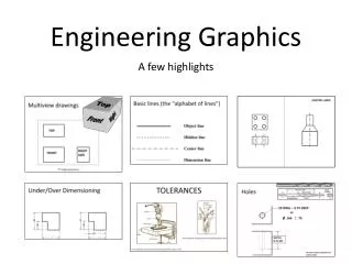
Engineering Drawing The engineering drawings are used to communicate and document the design process.
What you will learn • Visualization • Graphics Theory • Standards • Conventions • Tools • Applications
The “Language” Lines may be defined as……. • A series of points in space organized in a rational order • 2. The shortest distance between two points • 3. The geometry created by the intersection of two planes or surfaces • 4. A set of points organized that have length and direction, but no thickness
The “Language” Lines come in all types and shapes: Parallel lines will always maintain the same distance from each other throughout their entire length, and NEVER touch!
The “Language” Lines come in all types and shapes: Non-parallel lines do not maintain the same distance from each other throughout their entire length, and may either touch, or eventually cross each other.
The “Language” Lines come in all types and shapes: Perpendicular lines are at 90 degrees to one another.
The “Language” Lines come in all types and shapes: Intersecting lines cross each other at any angle.
The “Language” Lines come in all types and shapes: Tangent lines are created when: 1. A curved and straight line meet, and…. 2. The two lines intersect at only one point, and…. 3. A smooth transition into one line can be generated.
The “Language” Lines come in all types and shapes: Lines will appear as edges when there is an intersection of two planes or surfaces.
The “Language” Lines come in all types and shapes: Tangent conditions may appear in both 2D and 3D geometry…. Figure A shows a tangent being created at Point C Figure B shows Tangent F being identified as the intersection point between the 2 circles.
The “Language” Lines come in all types and shapes: Here we can see that Line VT is lying tangent to the cone.
The “Language” Lines come in all types and shapes: Can you explain why Example A is tangent, but Example B is not??
The “Language” Circles are considered the most perfect form geometric shape. All circles are made up of many parts…
The “Language” A parabola’s shape can be generated from a 3D cone and 2D plane… Notice that the parabola’s shape is symmetrical (mirror image of itself), and that it has a focus point inside the arc of the line. The cutting plane is always parallel to the slope of the cone.
The “Language” Parabolas have many engineering uses and shapes… As the shape of the curve of the parabola changes, it allows for more diverse applications.
The “Language” The ellipse is generated in much the same way as the parabola… Notice that the ellipse’s shape is symmetrical (mirror image of itself), like the parabola. However, the ellipse has no focus point identified inside the arc of the line, and the cutting plane is NOTparallel to the slope of the cone.
The “Language” A circle may appear as an ellipse when the object is not perpendicular to the line of sight. While the circle’s geometry remains true shape and size, our view of its shape appears more oval as the object is rotated from its 90 degree position.
The “Language” Lines can be set at angles to points or other lines… Lines set at angles help us understand the relationship of other lines, or the geometry’s position in space.
The “Language” Quadrilaterals have two main characteristics: • They are CLOSEDentities, • 2. They have 4 sides.
The “Language” Polygon means “many sided”: Most polygons have names based on the number of sides they have.
The “Language” 2D and 3D Space: Let’s take a few minutes to see how lines and points are used to organize space…..
The “Language” If we take the centre of the universe as our home position (X=0 and Y=0) , we are able to map out the coordinate vertices of any object from that point and assign them addresses so they may be easily located.
The “Language” However, as the universe is not 2-dimensional, we must take into consideration a 3rd axis (Z) that represents its volume.
The “Language” However, as the universe is not 2-dimensional, we must take into consideration a 3rd axis (Z) that represents its volume.
The “Language” Since the computer ALWAYS remembers that its home is (0,0,0), we may locate any point in space, or on a 3D model, by referencing home.
The “Language” Each point on a 3D model has its own address in space that is designated by an X, Y, & Z value. Here we can see the address of each vertex. Example: (4, 3, 0)
Isometric Drawing Isometric drawing is made up of a series of parallel vertical lines and parallel 30 degree lines.
Isometric Crating Crating is a term used for cutting away from a shape. The easiest shape to draw is a block and this can serve as a guide and will give the overall size of the object to be drawn. Below is an example of a step shape being drawn in a guide block.
Homework1 WebPage Due, Thursday, February 02, 2012 Omar E. Meza Castillo Ph.D.