Mastering Engineering Graphics: A Comprehensive Course in CAD & Technical Drawing
290 likes | 388 Views
Dive into the world of engineering graphics, exploring the language used in design processes, with a focus on conventions, standards, and the alphabet of lines. Learn about tools, scale reading, and CAD software, enhancing your technical sketching skills and understanding common types of projections. Explore sketching techniques and lettering standards as you navigate through the fundamentals of AutoCAD 2015.

Mastering Engineering Graphics: A Comprehensive Course in CAD & Technical Drawing
E N D
Presentation Transcript
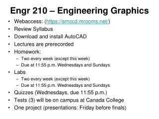
Engr 210 – Engineering Graphics • Webaccess: (https://smccd.mrooms.net/) • Review Syllabus • Download and install AutoCAD • Lectures are prerecorded • Homework: • Two every week (except this week) • Due at 11:55 p.m. Wednesdays and Sundays • Labs • Two every week (except this week) • Due at 11:55 p.m. Wednesdays and Sundays • Quizzes (Wednesdays, due 11:55 p.m.) • Tests (3) will be on campus at Canada College • One project (presentations: Friday before finals)
Engineering Graphics • Engineering graphics is a real and complete language used in the design process for: 1. Thinking 2. Communicating 3. Solving problems 4. Quickly and accurately visualizing objects. 5. Conducting analyses. • In engineering, 92 percent of the design process is graphically based. The other 8 percent is divided between mathematics, and written and verbal communications.
Standards And Conventions • Conventions are commonly accepted practices, rules, or methods used in technical drawing. • Standards are sets of rules that govern how technical drawings are represented. • Standards allow for the clear communication of technical ideas. • In the United States, the AmericanNational Standards Institute (ANSI) is the governing body that sets the standards used for engineering and technical drawings. • Other professional organizations, such as the American Society for Mechanical Engineering (ASM), assist ANSI in developing technical graphics standards.
Alphabet of Lines • Center lines are used to represent symmetry and paths of motion, and to mark the centers of circles and the axes of symmetrical parts, such as cylinders and bolts. • Visible lines are used to represent features that can be seen in the current view. • Hidden lines are used to represent features that cannot be seen in the current view. • Dimension and extension lines are used to indicate the sizes of features on a drawing. • Section lines are used in section views to represent surfaces of an object cut by a cutting plane. • Cutting plane lines are used in section drawings to show the location of a cutting plane.
Traditional Tools 1. Wood and mechanical pencils. 2. Instrument set, including compass and dividers. 3. 45- and 30/60-degree triangles. 4. Scales. 5. Irregular curves. 6. Protractors. 7. Erasers and erasing shields. 8. Drawing paper. 9. Circle templates. 10. Isometric templates.
Computer-Aided Design Tools • A CAD system consists of hardware devices used in combination with specific software. • The hardware for a CAD system consists of the physical devices used to support the CAD software. • In this class, we will be using AutoCAD 2015 & SolidWorks as our CAD software.
Sketching Technical Sketching • The process of producing a rough preliminary drawing representing the main features of a product or structure • Traditionally done freehand (can also use CAD) Common Types of Projections • Multiview • Axonometric • Oblique • Perspective
Sketching Process • Based on the interactive process of seeing, imaging and representing
Sketching Techniques 1. Contour Sketching – sketching the outline of an object. Contours: edges of an objects, lines separating contrasting light or color, changes in surface, and overlapping parts. Slowly move your pencil across the paper as your eye scans the outline of the object. 2. Negative Space Sketching – focus on the spaces between objects and not the objects themselves. 3. Upside-Down Sketching – turn a recognizable object upside-down before sketching (concentrate on shape and form).
Contour Sketch: Focus on observing outline of object, not the paper.
Negative Space Sketching - Focus on spaces between or around the objects, not on object itself.
Lettering Standards American National Standards Institute (ANSI): • Use a Gothic text style, either inclined or vertical • Use all capital letters • Use 1/8” (3 mm) for most text height • Use ¼” (6 mm) for fractions • Minimum space between lines: Text height divided by 3.
Lettering Recommended Text Heights: Guide Lines Spacing:
Text on Drawings • Title Block • Revision Block • Bill of Materials • General Notes
AutoCAD 2015 Basics AutoCAD Window: A. Title Bar - name of program B. Menu Bar - common applications (filing viewing, edit, graphics operations) • Standard Toolbar - icons for frequently used commands such as Redraw, Undo, Zoom, Open, Save, etc. Buttons with small black triangles in the lower-right corner have flyouts of related commands D. Object Properties Toolbar - Sets object properties such as color, linetype, and lightweight
AutoCAD Basics (cont.) E. Draw and Modify Toolbars - (must be displayed all the time) F. Drawing Area • Cursor - used to locate points, and select and draw objects H. User Coordinate system (UCS) icon I. Model Tab/Layout Tabs - switch your drawing between model (drawing) space and paper (layout) space.
AutoCAD Basics (cont.) J. Command Window - displays prompts & messages Starting a Command: 1. Choose an item from a menu 2. Click button on a toolbar 3. Enter a command on the command line K. Status Bar • displays the cursor coordinates in the lower-left corner • also displays a description of the different functions and icons as the mouse cursor is moved over different areas • buttons for turning on drawing aids: Snap, Grid, Ortho, Polar, Osnap, Otrack, Lwt, and Model
[Esc] - Canceling commands • The [Esc] key is used to cancel a command in AutoCAD 2015. The [Esc] key is located near the top-left corner of the keyboard. Sometimes, it may be necessary to press the [Esc] key twice to cancel a command; it depends on where we are in the command sequence. For some commands, the [Esc] key is used to exit the command. • On-Line Help • Online Resources: Click on the HELP option in the pull-down menu to access the AutoCAD 2015 Help menu system. • Standard Toolbar: Click on the [?] icon in the Standard toolbar to access Autodesk On-line Help: User Documentation. • Command line and function key: Press the [Fl] key or enter a question mark [?] at the command prompt to access the AutoCAD Online Help system.