Download
1 / 30
300 likes | 437 Views
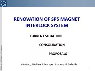
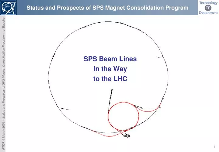
Status and Prospects of SPS Magnet Consolidation Program. SPS Beam Lines In the Way to the LHC. Outline. Introduction. Auxiliary magnets and equipment Magnets Equipment. Main magnets Erosion Fatigue Statistics 2008 – 2009. Prospects for 2009… 2010.

E N D
Status and Prospects of SPS Magnet Consolidation Program SPS Beam Lines In the Way to the LHC
Outline Introduction Auxiliary magnets and equipment • Magnets • Equipment Main magnets • Erosion • Fatigue • Statistics 2008 – 2009 Prospects for 2009… 2010 Impact of non shutdown 2009 – 2010 Conclusion
Outline Introduction Auxiliary magnets and equipment • Magnets • Equipment Main magnets • Erosion • Fatigue • Statistics 2008 – 2009 Prospects for 2009… 2010 Impact of non shutdown 2009 – 2010 Conclusion
Introduction - Magnets in the Way to the LHC • January 2008: ‘MTTR and Spare Policy for SPS Magnets’ has been adressed by D. Smekens to ATC-ABOC days Main magnets, continuousrefurbishment program New magnets in injection lines TI2/8, sparesavailable Criticalsince large familieswith few spares, but magnets are quitereliable Large families Courtesy of D. Smekens
Introduction • Reminder of the conclusions: • No specific risks for auxiliary magnets: generally small families of magnets with spares available for most of them • Main magnets are top priority since they constitute the largest families with few spares, and have a high risk of breakdown due to important solicitations (operated at saturation, high water flow speeds, no valves…) • need close monitoring of performance and early detection of possible accumulation of breakdowns that could be forerunner of illness (e.g. water leaks erosion) • Main scope of this presentation will be the main magnets
Outline Introduction Auxiliary magnets and equipment • Magnets • Equipment Main magnets • Erosion • Fatigue • Statistics 2008 – 2009 Prospects for 2009… 2010 Impact of non shutdown 2009 – 2010 Conclusion
Auxiliary Magnets • Several issues in auxiliary magnets could perturb the operation of the LHC: • Few spares are available for several magnet families most of which are mandatory for the LHC operation (MPLV, MPSV, LS/LSN, LO/LON, B340…) • Large majority of the spare magnets are not tested could increase MTTR if there is a magnet failure • Use of spare magnets for new projects (e.g.HiRadMat) could lead to a significant decrease of available spares for some families (MDSV, MBS) • Many of transfer line quadrupoles (QTL, QTA, QNL) have degraded shimming that can generate coil movements low reliability (water leaks, short-circuits to ground), but many spares are available from WEA • However, inspections led on the auxiliary magnets at the beginning of this shutdown have shown no major reliability issue • Our goal is now to have at least 1 operational spare (tested) for each magnet type ASAP
Auxiliary Equipments • Breakdowns of ancillary equipment that could also impact on accelerator operation: • Degradation of water hoses in use for more than 12 years need to be replaced (≈10 Km of hoses, ≈5000 fittings) to be done (TE/MSC) • Flashover between busbars need inspection and cleaning To be completed at the same time as water hoses replacement (TE/MSC) • Failure of water cooled cables (no spares installed, no spares available at the moment) investigations of risks of erosion inside cooling ducts inside cables in progress (collaboration TE/MSC – EN/EL) • Reliability issues of installation vehicles used for main magnets need complete refurbishment and upgrade for future projects in progress by EN/HE • Risk score to suffer such an event can be kept very low if appropriate actions are undertaken / pursued
Outline Introduction Auxiliary magnets and equipment • Magnets • Equipment Main magnets • Erosion • Fatigue • Statistics 2008 – 2009 Prospects for 2009… 2010 Impact of non shutdown 2009 – 2010 Conclusion
Main Magnets – Erosion Issues Usual issues are linked to ageing which is translated in erosion and fatigue phenomenon's • Erosion In places where high flow speed crosses sharp transitions effect is critical in thin copper tubes: water leaks • In dipoles: • Lintott coils (2/3 of MBB’s): due to design of the coil, flow reaches 9 m/s in some places. Consolidation program achieved over the 3 last shutdowns to replace all manifolds by improved design: 255 magnets in the machine equipped with these coils + all spares (even with Alsthom coils) have been refurbished Original design New design
Main Magnets – Erosion Issues • Alsthom coils (1/3 of MBB’s + all MBA’s): erosion induced water leaks also occur in these coils, but at a much lower rate than in Lintott coils. Also, leaks are generally located in non conform manifolds in which the section has been thinned or deformed by a bump (generation of higher flow speed and turbulences) or in which the wall thickness has been decreased by grinding Inspection during this shutdown has shown non conform manifolds on 24 magnets: deformed parts of tubes have been replaced to lower the risk of leaks. However, a consolidation (upgrade) like Lintott’s should be necessary sooner or later Bumps Grinded tube Tube partiallyreplaced
Main Magnets – Erosion Issues • In quadrupoles: 1 erosion induced water leak occurred at the end of run 2008. • Phenomenon is currently being studied. Recent endoscopies have already shown it is not a generalized problem,but quiteextended. Following results, a consolidation could be necessary soon (next shutdown ?). A solution consisting in the replacement of all thin tubes could be implemented in 1 shutdown in situ. Water leak Erosion craters
Main Magnets – Fatigue Issues • Fatigue Due to tens of million of pulses accumulated over 35 years of operation (although SPS initially designed for 50,000 h !) effect translates in different manners among the magnet families: • In dipoles: • Break of the fastening screws of the magnetic correction pole shim : phenomenon discovered this shutdown during inspection under magnet patrol access mode (main magnets pulsed). Currently being studied with help of EN/MME/MM 2 pole shim sets ateach end of dipoles
Main Magnets – Fatigue Issues • Pole shim system designed to adjust the magnetic length to match it with a reference magnet by adding lamination on pole ends (reproducibility of integrated field) M8 cylindrical head screws, steel class 12.9 1 to 10 laminations added (th.1.5mm) Spring pins
Main Magnets – Fatigue Issues In total, 26 pole shims were found defective on 18 magnets (16 MBB’s and 2 MBA’s) Possible causes: non conform mounting (unadapted screw length or tightening torque) high number of occurences could be due to accumulation over last 2 or 3 years (not detected during previous inspections ?) to be checked with results of future inspections sollicitations of run 2008 were more intense, with return of pulses at 450 GeV/C. Indeed, previous occurrences were already encountered during operation at 450 GeV/c between 1980 and 2000. Brokenhead of screwtrimminginto the vacuum chamber and the coilinsulationateach pulse Head of fasteningscrew and spring pin broken Pole shimmovingawayfromits position Magnetic correction laminationsfallingapart
Main Magnets – Fatigue Issues Consequences: degradation of the magneticfieldquality of the magnetsduringoperation (someshimswerefound on the ground) degradation of the coilinsulationleading to short-circuits to ground (1 case foundduring HV test): the end shimdisplaceddiagonallytrimsinto the insulation of the coil Strategy to consolidate: • 1st step: repairing of the broken pole shims found this shutdown before the SPS restart in march • Only 40% could be repaired in a corresponding way (i.e. with new screws and pins) • For the 60% remaining, impossible to remove both screws in situ laminations and end shim had to be glued. In addition, dismountable external fastening devices are being manufactured to allow keeping the pole shims in place up to next shutdown ( consolidation) • 2nd step: analysis of the phenomenon to define if upgrade of the system is needed • Analysis of broken screws collected (EN/MME/MM) in progress • Computations of a model + tests in laboratory to be done during run 2009
Main Magnets – Fatigue Issues • 3rd step: implementation in situ of solution based on results of study • If no or small upgrade is required, replacement of the screws (≈6000 units) with appropriate mounting by screws of same size (other steel quality could be chosen) • If upgrade is required, need to develop adapted tools to allow modifications (M8 M10) in situ (few space available) In both cases, has to be done (or at least started) during next shutdown MBB isometricview – connectionside
Main Magnets – Fatigue Issues • Longitudinal displacement of coil inside the yoke: phenomenon discovered on 5 dipoles (3 MBA’s, 2 MBB’s) during this shutdown inspection. Coils are shifted up to 40 mm towards connection side, in some cases pushing the vacuum chamber of the dipole upstream. • Possible causes: accumulation of movements over the years (neverdetectedbeforebecause amplitude of movementwastoosmall?) ; degradation of soft shimming ; kapton foil wrappedbetweencoil and yokedecrease friction coefficient ; pulses at 450 GeV/C ? • Disassembly of the magnets (run 2009) willproduce more information Coilshifted of 30 mm w.r.t. nominal position Vacuum chambertrimminginto the coilinsulation
Main Magnets – Fatigue Issues • Consequences: degradation of the magneticfieldquality of the magnetsduringoperation (corrections done by BE/OP last runseem to coroboratethisfact), degradation of the coilinsulationleading to short-circuits to ground • Actions: • - All magnetswiththisproblem have been replaced • - Measurementcampaign of longitudinal position of all coilsisbeingcompleted • - Adaptedcoilretainerscouldbedesignedduringnextrun and put in placeduringnextshutdown (e.g.Vetronite blocs put down on the magnetfeet) Coilretainerinstalled in the machine (Vetronit plate and blocks)
Main Magnets – Fatigue Issues • In quadrupoles (QD/QF) and enlarged quadrupoles (QFA/QDA): • Coil movements: due to degradation of soft shimming between coil and yoke (radiation, temperature, hardening). Result in fatigue of the copper tubes and brazed junctions of the manifolds water leaks • Corrective action for QD/QF: preventive exchanges (average of 3 / shutdown) and continuous refurbishment activity in adapted facility in radioactive workshop b.867 • Corrective action for QDA/QFA: shimming in situ with Vetronite pieces glued with Araldite since no reconstruction facility / procedure are available at the moment. 3 spare magnets are available (1 fully operational) for 14 magnets operated SPS Main quadrupole SPS Main enlargedquadrupole
Statistics Main Magnets 2008 - 2009 • Results: 5 interventions during run period, 15 magnet exchanges during shutdown period (3 for vacuum chamber coating project SPSU) Interventions run 2008 & magnet exchanges shutdown 2009 on main magnets Breakdown statisticsrun 2008 – shutdown 2009 on main magnets
Outline Introduction Auxiliary magnets and equipment • Magnets • Equipment Main magnets • Erosion • Fatigue • Statistics 2008 - 2009 Prospects for 2009… 2010 Impact of non shutdown 2009 – 2010 Conclusion
Prospects for 2009… 2010 • Refurbishment of all spare main magnets (taken out of the machine + in storage) during next shutdown, to be ready if we should encounter drastic reliability issues (pole shims on dipoles, waterleaks in quadrupoles…) • Prepare at least 1 spare magnet fully operational for each magnet type, starting by highest risk scores = f (impact on LHC and other facilities, ratio number of magnets in operation to number of spares, reliability) • Design and prepare implementation of pole shim consolidation + coil retainers • Prepare manifold consolidation ofquadrupoles • Prepare a global replacement campaign of the rubber water hoses in the whole SPS complex • If resources available, restart QTL/QTA refurbishment program
Outline Introduction Auxiliary magnets and equipment • Magnets • Equipment Main magnets • Erosion • Fatigue • Statistics 2008 – 2009 Prospects for 2009… 2010 Impact of non shutdown 2009 – 2010 Conclusion
Impact of non shutdown 2009-2010 • Program of magnet maintenance mainly based on results of general inspection performed in magnet patrol access mode at the beginning of the shutdown gives a complete overview of the state of magnets, allows early detection of illnesses and leads to preventive and corrective actions on the magnets (exchanges, modifications, upgrades…) • Scenario with no shutdown seems unrealistic, moreover with an operation at 450GeV/c which makes more demands on the magnets could decrease drastically the reliability of the machine without any signs (if no inspections) • Considering a scenario with a shortened shutdown (2 weeks of effective work), the following actions would be mandatory to ensure a quite reliable operation of the magnets in the SPS complex as LHC injector (i.e. except TDC2 and NEA): • High tension test on the main magnet system (magnets, busbars, water-cooled cables) in collaboration with TE/EPC + test of the imbalanced current detector: ½ day, machine closed ; • Inspection of the main magnets in the ring (access mode ‘magnet patrol’) + magnets in the transfer lines (mainly QTL’s in TT40 and TT60): 3 days (1 to open the covers, 1 for the inspection (machine closed), 1 to close the covers) • Exchange (not preventive, only corrective) or repairing of the defective magnets (pole shim screws broken, water leaks, short-circuits detected with the HV test…): approximately 1 day / magnet, following the type of defect ; • Therefore, main impact would be that neither preventive exchanges of magnets nor programs explained before (consolidation of pole shims, replacement of water hoses…) would be possible risk to decrease reliability
Outline Introduction Auxiliary magnets and equipment • Magnets • Equipment Main magnets • Erosion • Fatigue • Statistics 2008 – 2009 Prospects for 2009… 2010 Impact of non shutdown 2009 – 2010 Conclusion
Conclusions • Recent findings confirm what we already know: the SPS main magnets suffer ageing issues, and need maintaining if one wants to operate this machine for some additional decades with the LHC • Careful monitoring of the magnet performance by frequent inspections is the only way to avoid suffering drastic reliability issues. With ~1000 units over 2200 in the way to the LHC, they are the keystones of the SPS link in the injector chain • Consolidation of pole shims and quadrupole manifold refurbishment have to be done soon to ensure reliable operation • We strongly recommend to have at least one short shutdown to perform careful inspections
References • MTTR & Spare Policy for the LHC Injectors & Exp. Areas, David Smekens • Report to the PAF WG on the Status of the Magnets in the Existing Accelerators, W. Kalbreier, S. Ramberger, D. Smekens, T. Zickler, K. H. Mess • SPS Main Dipole Exchanges in 2007 & Next Shutdown Work, J. Bauche, W. Kalbreier, D. Smekens • New Strategy for the Repair of SPS Dipole Water Manifolds, J. Bauche, S. CettourCavé, W. Kalbreier, D. Smekens(EDMS Doc. No.: 783313)
Annex 1: Overview of the Complex SPS as LHC Injector • SPS as LHC injectorincorporate: • TT10 Beam Transport Tunnel fromPS extraction (TT2) to SPS Injection point in Sextant 1 • SPS Main Ring • TT40/TI8 injection tunnel; • TT60/TI2 injection tunnel; • 13500 m of beam line • 2200 magneticelements on LHC way