Download
1 / 11
110 likes | 143 Views
COBRA Magnet Status. W.Ootani MEG Experiment Review Meeting, Jul. 2004. COBRA Excitation at π E5. Apr.13 COBRA installation Apr.13-15 Cryostat evacuation Apr.16-19 Cooling Apr.21-26 Excitation Excitation test (Superconducting Magnet(SC) and Compensation Coils(NC))

E N D
COBRA Magnet Status • W.Ootani • MEG Experiment Review Meeting, Jul. 2004
COBRA Excitation at πE5 • Apr.13 COBRA installation • Apr.13-15 Cryostat evacuation • Apr.16-19 Cooling • Apr.21-26 Excitation • Excitation test (Superconducting Magnet(SC) and Compensation Coils(NC)) • Fringing field measurements and test of active shielding in πM3 • PMT test for Timing counter inside COBRA • PMT test for LXe calorimeter near COBRA • Apr.29 Beam is back
COBRA Installation in πE5 • COBRA placed at almost right place on beam line without platform.
Excitation at πE5 • Only 4days for cooling thanks to LN2 pre-cooling. • Both SC and NC successfully tested at full operating current. (The first time to fully test NC.) • COBRA provided perfectly stabilized field (ΔB/B<0.05%) for PMT tests.
Fringing Field Measurements Fringing field measured at πE5 [Gauss] 4.2 6.8 9.1 6.7 18.5 83.8 50.5 9.0 33.5 433.7 440.3 31.2 7.5 20.4 73.3 56.3 69.7 19.8 7.8 11.6 11.3
Fringing Field Measurements Fringing field measured outside area [Gauss] 0.5 1.6 1.6 1.6 8.4 6.1 4.0 πE5 2.1 3.3 4.8
Fringing Field Measurements Requirement Measured μE1< 20mG Neighboring area 0.5G πE3 μLan < 1G μCap < 1G 2-4G ECRIT< ?G 1-2G πE5 πM32 GPS < 20mG 1.8G πM33 LTF < 20mG 0.3G πM3 beam line Kicker < ?G Septum < ?G 3.3G 4.8G
Fringing Field Measurements • Fringing field was measured as predicted (unfortunately). • The problems are being fixed for most places. • Fringing field was successfully compensated in μSR facilities at πM3 using compensating coils. Control system has to be implemented. • Fringing field at πE3 seems possible to be reduced < 1G by passive shielding. • Detector at ECRIT did not work when COBRA was ON. • Effect on kicker and septum in πM3 beam line has to be checked.
Possible Solution in πE3 • Installation of active shielding in the detector (μLAN, μCAP) is difficult because of limited space and cost(?). • Passive shielding • Shielding box built with 5mm-thick soft iron plates (5m-D, 4m-W, 3m-H) • No front wall for minimizing influence on beam optics • Roof might not be necessary. (For good accessibility) Without roof With roof Beam Beam
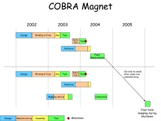
Summary • COBRA magnet was installed in πE5 and totally tested. • PMT tests were carried out by using COBRA field. • ΔB/B<0.05% • Stray field around LXe detector region is successfully canceled. • Fringing field was measured in the neighboring beam line and problems are being fixed. • It was found that active shielding is able to compensate COBRA field very well. • Calibration of field mapping machine will be made this year. • System alignment • Calibration of Hall sensors • Investigate possibility to use NMR • Field map reconstruction • Final field measurement is supposed to be carried out during shutdown period in 2006 after beam line commissioning is finished.
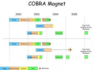
Schedule Feb. 2004 Jul. 2004