Download
1 / 32
320 likes | 544 Views
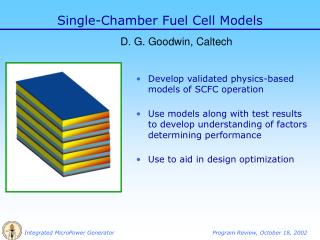
Single-Chamber Fuel Cell Models. D. G. Goodwin, Caltech. Develop validated physics-based models of SCFC operation Use models along with test results to develop understanding of factors determining performance Use to aid in design optimization. Multiple models. Computational expense.

E N D
Single-Chamber Fuel Cell Models D. G. Goodwin, Caltech • Develop validated physics-based models of SCFC operation • Use models along with test results to develop understanding of factors determining performance • Use to aid in design optimization
Multiple models Computational expense • Model 1: a simple model for qualitative parametric studies • Allows rapid exploration of the effects of various parameters on performance • Model 2: Solves 2D channel flow assuming fully developed flow. Computes • Species concentration profiles • Current density profiles • Power output vs. load • Model 3: Solves 2D reacting channel flow accurately (in development, Yong Hao) Seconds on a laptop PC Minutes on a linux workstation Minutes to hours
Can be used to model single- or dual-chamber designs No consideration of gas flow Approximate equilibrium treatment of hydrocarbon oxidation Includes diffusion through electrodes, activation polarizations, ohmic losses Can compute current-voltage curves Written in a simple scripting language (Python) Uses the Cantera software package to evaluate thermodynamic and transport properties, and compute chemical equilibrium (www.cantera.org) Good for semi-quantitative parametric studies Model 1: a “zero-dimensional” fuel cell model
Uniform cathode-side gas Porous Cathode Porous Anode Uniform anode-side gas Idealized Geometry • Each side exposed to uniform gas with specified composition • No depletion in gas • Corresponds to limit of fast transport • Compositions can be set equal (single-chamber) or each independently specified (dual-chamber)
Electrochemical Reactions • Anode reactions • H2 + O2- = H2O • CO + ½ O2- = CO2 • Cathode reaction • O2 = 2O2- • Catalyst selectivity • Reactions allowed to occur at opposite electrode with relative rate 0 < Fc < 1 • Fc > 0 lowers OCV • At Fc = 0, OCV = 0
Gas Composition Inlet gas equilibrium gas • Approximate treatment of partial oxidation • Assume gas is a mixture of the input gas composition + equilibrium composition • No selectivity assumed – CO, CO2, H2, and H2O all present Feq 1 - Feq Input: 1:3:12 C3H8/O2/He partially-oxidized gas mixture 600 C
concentration gradients in electrode drive diffusion product Assumed uniform gas composition reactant electrode Transport through electrodes • Gas composition at electrode/electrolyte interface determined by diffusion through porous electrode • Effective diffusion coefficients account for pore size, porosity, and tortuosity of electrode microstructure • Concentrations at electrode/electrolyte interface used to calculate Nernst potential
Cathode Activation Polarization • Represents largest loss • Dependence on oxygen partial pressure assumed first-order Range considered
Anode Activation Polarization • Assumed not to be rate-limiting • Anode exchange current density set to a large multiple of cathode exchange current density (100 – 1000)
Electrolyte Ohmic Loss Value for GDC used
Current Density Computation • Nernst potential calculated using concentrations at electrode/electrolyte interfaces, and includes effects of back reaction • Given Eload, this equation is solved for the current density
Simulation of Test Results with Ni-SDCSDCSSC-Pt-SDC at 600 C
Test results can be accounted for with physically-reasonable parameters • Experimental Ni-SDCSDCSSC-Pt-SDC results at 600 C best fit by • I0,c = 70 mA/cm2 • 80% electrode selectivity • 50% conversion to equilibrium products Accurate modeling of transport limit requires more accurate treatment of transport processes – see Model 2 results
Gas Composition Effects • Increasing percent conversion to equilibrium products moves the transport limit to higher current densities • For fuel-rich input mixtures, equilibrium composition contains significant CO and H2, in addition to CO2 and H2O • Therefore, non-electrochemical oxidation of CO and H2 not likely to be a problem as long as a fuel-rich mixture is used 60% 10%
Single Chamber vs. Dual Chamber • Dual chamber calculation sets cathode gas composition to air, and eliminates the back reactions at the electrodes Dual Single
Catalyst selectivity effects Catalysts must have reasonable selectivity for electrochemical reactions in order for SCFC to function More selective Less selective
SCFC Loss Mechanisms • Dominated by losses due to • Low cathode activity • Incomplete cathode and anode selectivity
Model Overview • Inputs • Inlet gas composition, temperature, pressure • Load potential • Parameters characterizing kinetics, electrode transport, geometry, etc. • Outputs • 2D spatial distributions of C3H8, CH4, CO, H2, CO2, and H2O in channel • Current density profile J(x) • Assumes isothermal, isobaric conditions • Includes an unsealed, non-catalytic plate (interconnect) separating anode and cathode gas streams
Anode Model Geometry Electrolyte Cathode Cathode-side flow channel Premixed Fuel / air mixture Non-catalytic partition Anode-side flow channel
Species equations finite-differenced and integrated in time to steady state. Porous electrodes handled by locally modifying diffusion coefficients Species equations solved simultaneously with equation for current density Mathematical Model
Model Problem • Channel height = 700 mm, length = 10 mm • 200 mm anode, 50 mm cathode • Electrode porosity 0.4, pore size 0.1 mm • 15 mm GDC electrolyte • T = 600 C, P = 1 atm • Premixed 1:3 C3H8 / air • Partial oxidation rate at anode set to give nearly complete consumption of propane • Other parameters same as in zero-D model
reactants products reaction Porous Electrode Transport • Gas must diffuse through porous electrodes to reach electrochemically-active triple-phase boundary • Process modeled with effective diffusion coefficients for each species that interpolate between Knudsen and ideal gas limits • Effective diffusion coefficient close to the Knudsen limit
Partial Oxidation • Global partial oxidation reaction C3H8 + 3/2 O2 => CO + 4H2 • Produces electrochemically-active species • assumed to occur throughout the anode • May occur on the cathode also • Rate modeled as first-order in C3H8 and O2 • Magnitude set to lead to nearly complete conversion in the anode-side exhaust • ample residence time for complete conversion (50-100 ms vs. 1 ms) • Degree of conversion can be tuned experimentally by material choice, and anode fabrication methods
Velocity Profile This velocity profile is imposed, based on known solution for viscous fully-developed flow Porous cathode Porous anode
Species Distributions at Max Power Cathode on right Anode on left flow
Current Density Distribution • Movie shows steady-state J(x) for load potentials ranging from zero to 0.9 V
Predicted Performance at 600 C • Predicted OCV = 0.9 V, peak power density = 85 mW/cm2 • Easily meets target SCFC performance of 50 – 100 mW/cm2.
Conclusions • Performance targets appear to be easily achievable • Largest potential gains in performance: • improved cathode catalytic activity • improved electrode selectivity • Separator plate may not be necessary • As long as gas composition is fuel rich, non-electrochemical oxidation of CO and H2 will not go to completion, and therefore nonselective catalyst for partial oxidation is acceptable.
Future Work • Validation against all available test data – single-chamber, dual-chamber, etc. • Prediction of coking behavior • Prediction of low-temperature performance • Integration with Swiss Roll heat exchanger model to predict operating temperature
Summary • Two numerical models have been developed to predict SCFC performance. • A simple model useful for interpreting test data • A channel flow model useful for predicting micropower generator performance • Test results can be accounted for with physically-reasonable kinetic parameters • Using these parameters in the channel-flow model leads to performance at 600 C that meets our targets • Both models are suitable for use in design and optimization studies, including system studies with the Swiss Roll heat exchanger.