Download

1 / 51
540 likes | 618 Views
Explore the history, basics, types, benefits, and current initiatives of fuel cell technology. Learn about thermodynamics, components, and future prospects in this eco-friendly energy source.

E N D
Topics 1. A Very Brief History2. Electrolysis3. Fuel Cell Basics - Electrolysis in Reverse - Thermodynamics - Components - Putting It Together4. Types of Fuel Cells - Alkali - Molten Carbonate - Phosphoric Acid - Proton Exchange Membrane - Solid Oxide5. Benefits6. Current Initiatives - Automotive Industry - Stationary Power Supply Units - Residential Power Units7. Future
A Very Brief History Considered a curiosity in the 1800’s. The first fuel cell was built in 1839 by Sir William Grove, a lawyer and gentleman scientist. Serious interest in the fuel cell as a practical generator did not begin until the 1960's, when the U.S. space program chose fuel cells over riskier nuclear power and more expensive solar energy. Fuel cells furnished power for the Gemini and Apollo spacecraft, and still provide electricity and water for the space shuttle.(1)
Electrolysis “What does this have to do with fuel cells?” By providing energy from a battery, water (H2O) can be dissociated into the diatomic molecules of hydrogen (H2) and oxygen (O2). Figure 1
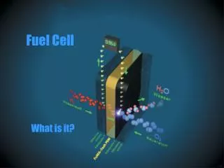
work fuel cell O2 H2O H2 heat Fuel Cell Basics “Put electrolysis in reverse.” The familiar process of electrolysis requires work to proceed, if the process is put in reverse, it should be able to do work for us spontaneously. The most basic “black box” representation of a fuel cell in action is shown below: Figure 2
H2(g) + ½O2(g) H2O(l) Table 1 Thermodynamic properties at 1Atm and 298K H2 O2 H2O (l) Enthalpy (H) 0 0 -285.83 kJ/mol Entropy (S) 130.68 J/mol·K 205.14 J/mol·K 69.91 J/mol·K Fuel Cell Basics Thermodynamics Other gases in the fuel and air inputs (such as N2 and CO2) may be present, but as they are not involved in the electrochemical reaction, they do not need to be considered in the energy calculations. Enthalpy is defined as the energy of a system plus the work needed to make room for it in an environment with constant pressure. Entropy can be considered as the measure of disorganization of a system, or as a measure of the amount of energy that is unavailable to do work.
Fuel Cell Basics Thermodynamics Enthalpy of the chemical reaction using Hess’ Law: ΔH = ΔHreaction = ΣHproducts – ΣHreactants = (1mol)(-285.83 kJ/mol) – (0) = -285.83 kJ Entropy of chemical reaction: ΔS = ΔSreaction = ΣSproducts – ΣSreactants = [(1mol)(69.91 J/mol·K)] – [(1mol)(130.68 J/mol·K) + (½mol)(205.14 J/mol·K)] = -163.34 J/K Heat gained by the system: ΔQ = TΔS = (298K)(-163.34 J/K) = -48.7 kJ
Fuel Cell Basics Thermodynamics The Gibbs free energy is then calculated by: ΔG = ΔH – TΔS = (-285.83 kJ) – (-48.7 kJ) = -237 kJ The external work done on the reaction, assuming reversibility and constant temp. W = ΔG The work done on the reaction by the environment is: W = ΔG = -237 kJ The heat transferred to the reaction by the environment is: ΔQ = TΔS = -48.7 kJ More simply stated: The chemical reaction can do 237 kJ of work and produces 48.7 kJ of heat to the environment.
Fuel Cell Basics Components Anode:Where the fuel reacts or "oxidizes", and releases electrons. Cathode:Where oxygen (usually from the air) "reduction" occurs. Electrolyte: A chemical compound that conducts ions from one electrode to the other inside a fuel cell. Catalyst: A substance that causes or speeds a chemical reaction without itself being affected. Cogeneration: The use of waste heat to generate electricity. Harnessing otherwise wasted heat boosts the efficiency of power-generating systems. Reformer: A device that extracts pure hydrogen from hydrocarbons. Direct Fuel Cell: A type of fuel cell in which a hydrocarbon fuel is fed directly to the fuel cell stack, without requiring an external "reformer" to generate hydrogen.
Figure 3 Fuel Cell Basics Putting it together.
Types of Fuel Cells • The five most common types: • Alkali • Molten Carbonate • Phosphoric Acid • Proton Exchange Membrane • Solid Oxide
Types of Fuel Cells SOFC Vorteil: Keine aufwendige Brenngas-Aufbereitung Nachteil: Hohe Betriebstemperaturen = Hohe System-Kosten Starke Material-Beanspruchung
Alkali Fuel Cell compressed hydrogen and oxygen fuel potassium hydroxide (KOH) electrolyte ~70% efficiency 150˚C - 200˚C operating temp. 300W to 5kW output Figure 4 requires pure hydrogen fuel and platinum catylist → ($$) liquid filled container → corrosive leaks
Molten Carbonate Fuel Cell (MCFC) carbonate salt electrolyte 60 – 80% efficiency ~650˚C operating temp. cheap nickel electrode catylist up to 2 MW constructed, up to 100 MW designs exist Figure 5 The operating temperature is too hot for many applications. carbonate ions are consumed in the reaction → inject CO2 to compensate
Phosphoric Acid Fuel Cell (PAFC) phosphoric acid electrolyte 40 – 80% efficiency 150˚C - 200˚C operating temp 11 MW units have been tested sulphur free gasoline can be used as a fuel Figure 6 The electrolyte is very corrosive Platinum catalyst is very expensive
Proton Exchange Membrane (PEM) thin permeable polymer sheet electrolyte 40 – 50% efficiency 50 – 250 kW 80˚C operating temperature Figure 7 electrolyte will not leak or crack temperature good for home or vehicle use platinum catalyst on both sides of membrane → $$
Solid Oxide Fuel Cell (SOFC) hard ceramic oxide electrolyte ~60% efficient ~1000˚C operating temperature cells output up to 100 kW Figure 8 high temp / catalyst can extract the hydrogen from the fuel at the electrode high temp allows for power generation using the heat, but limits use SOFC units are very large solid electrolyte won’t leak, but can crack
Benefits Efficient: in theory and in practice Portable: modular units Reliable: few moving parts to wear out or break Fuel Flexible: With a fuel reformer, fuels such as natural gas, ethanol, methanol, propane, gasoline, diesel, landfill gas,wastewater, treatment digester gas, or even ammonia can be used Environmental: produces heat and water (less than combustion in both cases) near zero emission of CO and NOx reduced emission of CO2 (zero emission if pure H2 fuel)
Review of Membrane (Nafion) Properties Chemical Structure Proton Conduction Process Water Transport and Interface Reactions Fuel Cell Fundamentals
Chemical structures of some membrane materials PSSA poly(styrene-co-styrenesulfonic acid) (PSSA) Nafion,TM Membrane C Dow PESA(Polyepoxy- succinic Acid) ,,-Trifluorostyrene grafted onto poly(tetrafluoro-ethylene) with post-sulfonation) Poly – AMPS Poly(2-acrylamido-2-methylpropane sulfonate)
Nafion Membrane Chemical Structure
Nafion Membrane Proton Conduction Process
The water transport through Nafion Membrane Water flux due to electroosmotic drag (mol/cm2 s) is: Nw, drag= I()/F. Where: I is the cell current, () is the electroosmotic drag coefficient at a given state of membrane hydration (=N(H2O)/N(SO3H) and F is the Faraday constant. This flux acts to dehyddrate the anode side of a cell and to introduce additional water at the cathode side. The buildup of water at the cathode (including the product water from the cathode reaction) is reduced, in turn, by diffusion back down the resulting water concentration gradient (and by hydraulic permeation of water in differentially pressurized cells where the cathode is held at higher overall pressure). The fluxes (mol/cm2 s) brought about by the latter two mechanisms within the membrane are: Nw,diff = -D()c/ z, Nw,hyd = -khyd()P/ z where D is the diffusion coefficient in the ionomer at water content , c/ z is a water concentration gradient along the z-direction of membrane thickness, khyd is the hydraulic permeability of the membrane, and P/ z is a pressure gradient along z.
The water transport through Nafion Membrane Many techniques have been introduced to prevent the dehydration of the anode (including the introduction of liquid water into the anode and/or cathode, etc. – which, however, can lead to “flooding” problems that inhibit mass transfer). However, the overall question of “water management,” including the issue of drag as a central component, has been solved to a very significant extent by the application of sufficiently thin PFSA membranes (<100 µm thick) in PEFCs, combined with humidification of the anode fuel gas stream. An example of a development specifically enabling this to an extreme degree is the developmental composite membrane introduced W. L. Gore that provides usable mechanical properties for very thin (20 µm and less) perfluorinated membranes with high protonic conductivity.
Water Transport (& Interface Reactions) in Nafion Membrane of the PEM Fuel Cell
Solid Oxide Fuel Cell Air side = cathode: High oxygen partial pressure O2 H2 + 1/2O2D H2O H2 H2O Fuel side= anode: H2 + H2O= low oxygen partial pressure
Chemical Reactions in 2 separated compartements: - Cathode (Oxidation): - Anode (Reduction): ½O2 + 2e-D O2- H2 + O2-D H2O + 2e- ½O2 + H2D H2O SOFC: Electromotive Force (EMF) DG = Free Enthalpie z = number of charge carriers F = Faraday Constant DG0= Free Enthalpie in standart state R = Gas Constant EMF of a galvanic Cell: (1) EMF = DGr /-z F (2) difference of DG between anode und cathode K Nernst Equation: A
Elektrochemische Potential Oxygen ions migrate due to an electrical and chemical gradient Electrochemichal Potential Chemical Potential Electrical Potential Driving force for the O2- Diffusion through the electrolyte are the different oxygen partial pressures at the anode and the cathode side: ji = ionic current si= ionic conductivity
engl. Open Circuit Voltage (OCV) What happems in case : • No current • Electrical potential difference = chemical potetial OCV
Leistungs-Verluste Under load decrease of cell voltage and internal losses U(I) = OCV - I(RE+ RC+RA) - hC - hA OCV (RE+ RC+RA) Ohmic resistances hC cell voltage U(I) [V] Non ohmic resistances= over voltages hA cell current I [mA/cm2]
Überspannungen • Over voltages exist at interfaces of • Elektrolyte - Cathode • Elektrolyte - Anode • Reasons: • Kinetichindrance of theelectrochemicalreactions • Bad adheasion of electrodeandelectrolyte • Diffusion limitationsathighcurrentdensities
Ohm‘s losses Past Future 800nm Anode Kathode Reduce electrolyte thickness
Leistungs-Verluste 1 2 3 • Open circuit voltage (OCV), I = 0 • SOFC under Load U-I curve • (3) Short circuit, Vcell = 0 (2) (3) (1)
Iinput Umeasured How to determine the electrical conductance Electrical resistance: Electrical conductivity: • U : voltage [V] • I : current [A] • R : resistivity [ohm] • DL : distance between both • inner wires [cm] • A : sample surface [cm2] • : conductivity [S/m] Ea : activation energy [eV] • T : temperature [K] • K : Boltzmann constant
SOFC Design Tubular design i.e. Siemens-Westinghouse design Segment-type tubular design Planar design i.e. Sulzer Hexis, BMW design
Tubular Design – Siemens-Westinghouse • Why was tubular design developed in 1960s by Westinghouse? • Planar cell: Thermal expansion mismatch between ceramic and support structures leads to problems with the gas sealing tubular design was invented • Advantages of tubular design: • At cell plenum: depleted air and fuel react heat is generated incoming oxidant can be pre-heated. • No leak-free gas manifolding needed in this design ! • Drawback of tubular design: • Electric current flows along circumference of anode and cathode high cell losses cathode interconnection cathode (air) air flow anode (fuel)
cathode (air) electrolyte anode (fuel) Tubular Design – Siemens-Westinghouse • To overcome problems new Siemens-Westinghouse „HPD-SOFC“ design: • New: Flat cathode tube with ligaments • Advantages of HPD-SOFC: • Ligaments within cathode short current pathways decrease of ohmic resistance • High packaging density of cells compared to tubular design Siemens-Westinghouse shifted from basic technology to cost reduction and scale up. Power output: Some 100 kW can be produced.
interconnect cathode (air) electrolyte anode (fuel) Planar Design – Sulzer Hexis • Advantages of planar design: • Planer cell design of bipolar plates easy stacking no long current pathways • Low-cost fabrication methods, i.e. Screen printing and tape casting can be used. • Drawback of tubular design: • Life time of the cells 3000-7000h needs to be improved by optimization of mechanical and electrochemical stability of used materials. • Power output: 1 kW is aimed.
Planar Design – BMW Air channel bipolar plate Cathode current collector cathode electrolyte anode porous metallic substrate Fe-26Cr-(Mo, Ti, Mn, Y2O3) alloy bipolar plate Application Batterie replacement in the BMW cars of the 7-series. Power output: 135 kW is aimed. Fuel channel Plasma spray 20-50 mm 5-20 mm Plasma spray Plasma spray 15-50 mm
Current Initiatives Automotive Industry Most of the major auto manufacturers have fuel cell vehicle (FCV) projects currently under way, which involve all sorts of fuel cells and hybrid combinations of conventional combustion, fuel reformers and battery power. Considered to be the first gasoline powered fuel cell vehicle is the H20 by GM: GMC S-10 (2001) fuel cell battery hybrid low sulfur gasoline fuel 25 kW PEM 40 mpg 112 km/h top speed Figure 9
Current Initiatives Automotive Industry Fords Adavanced Focus FCV (2002) fuel cell battery hybrid 85 kW PEM ~50 mpg (equivalent) 4 kg of compressed H2 @ 5000 psi Figure 10 Approximately 40 fleet vehicles are planned as a market introduction for Germany, Vancouver and California for 2004. Figure 11
Current Initiatives Automotive Industry Daimler-Chrysler NECAR 5 (introduced in 2000) 85 kW PEM fuel cell methanol fuel reformer required 150 km/h top speed Figure 12 version 5.2 of this model completed a California to Washington DC drive awarded road permit for Japanese roads
Current Initiatives Automotive Industry Mitsubishi Grandis FCV minivan fuel cell / battery hybrid 68 kW PEM compressed hydrogen fuel 140 km/h top speed Figure 13 Plans are to launch as a production vehicle for Europe in 2004.
Current Initiatives Stationary Power Supply Units More than 2500 stationary fuel cell systems have been installed all over the world - in hospitals, nursing homes, hotels, office buildings, schools, utility power plants, and an airport terminal, providing primary power or backup. In large-scale building systems, fuel cells can reduce facility energy service costs by 20% to 40% over conventional energy service. Figure 14 A fuel cell installed at McDonald’s restaurant, Long Island Power Authority to install 45 more fuel cells across Long Island, including homes.(2) Feb 26, 2003
Current Initiatives Residential Power Units There are few residential fuel cell power units on the market but many designs are undergoing testing and should be available within the next few years. The major technical difficulty in producing residential fuel cells is that they must be safe to install in a home, and be easily maintained by the average homeowner. Residential fuel cells are typically the size of a large deep freezer or furnace, such as the Plug Power 7000 unit shown here, and cost $5000 - $10 000. Figure 15 If a power company was to install a residential fuel cell power unit in a home, it would have to charge the homeowner at least 40 ¢/kWh to be economically profitable.(3) They will have to remain a backup power supply for the near future.
Future “...projections made by car companies themselves and energy and automotive experts concur that around 2010, and perhaps earlier, car manufacturers will have mass production capabilities for fuel cell vehicles, signifying the time they would be economically available to the average consumer.” Auto Companies on Fuel Cells, Brian Walsh and Peter Moores, posted on www.fuelcells.org A commercially available fuel cell power plant would cost about $3000/kW, but would have to drop below $1500/kW to achieve widespread market penetration. http://www.fuelcells.org/fcfaqs.htm Technical and engineering innovations are continually lowering the capital cost of a fuel cell unit as well as the operating costs, but it is expected that mass production will be of the greatest impact to affordability.
Future internal combustion obsolete? solve pollution problems? common in homes? better designs? higher efficiencies? cheaper electricity? reduced petroleum dependency? ...winning lottery numbers?