
Advanced Damped and Detuned Structures for CLIC Main Linacs
This paper presents a novel design approach for the main accelerating structures in the Compact Linear Collider (CLIC), focusing on High Phase Advance (HPA) structures that operate at 5π/6 phase advance per cell. The study explores their performance characteristics, including reduced electrical breakdown risk and optimized group velocities. Both fundamental and dipole modes in a Damped and Detuned Structure (DDS) are analyzed, contributing to greater beam dynamics efficiency, reduced input power requirements, and improved luminosity. Key findings suggest significant performance enhancements compared to standard structures.

Advanced Damped and Detuned Structures for CLIC Main Linacs
E N D
Presentation Transcript
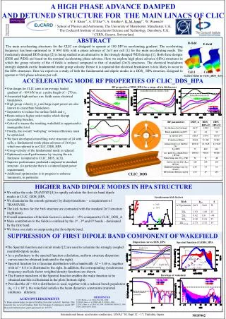
A HIGH PHASE ADVANCE DAMPED AND DETUNED STRUCTURE FOR THE MAIN LINACS OF CLIC V. F. Khan†*, A. D’Elia†*‡, A. Grudiev‡,R. M. Jones†*, W. Wuensch‡ † School of Physics and Astronomy, The University of Manchester, Manchester, U.K. * The Cockcroft Institute of Accelerator Science and Technology, Daresbury, U.K. ‡ CERN, Geneva, Switzerland. H-field E-field ABSTRACT The main accelerating structures for the CLIC are designed to operate at 100 MV/m accelerating gradient. The accelerating frequency has been optimised to 11.994 GHz with a phase advance of 2π/3 per cell [1] for the main accelerating mode. The moderately damped DDS design [2] is being studied as an alternative to the strongly damped WDS design [1]. Both these designs (DDS and WDS) are based on the nominal accelerating phase advance. Here we explore high phase advance (HPA) structures in which the group velocity of the rf fields is reduced compared to that of standard (2π/3) structures. The electrical breakdown strongly depends on the fundamental mode group velocity. Hence it is expected that electrical breakdown is less likely to occur in the HPA structures. Here we report on a study of both the fundamental and dipole modes in a DDS_ HPA structure, designed to operate at 5π/6 phase advance per cell. Cell 1 Cell 24 Surface fields in CLIC_DDS_A[3] ACCELERATING MODE RF PROPERTIES OF CLIC_DDS_HPA RF properties of DDS_HPA for a range of iris thicknesses • Our design for CLIC aims at an average loaded • gradient of ~100 MV/m at a pulse length of ~ 270 ns. • Associated high surface e.m. fields cause electrical • breakdown. • High group velocity (vg) and large input power are also • known to exacerbate breakdown. • Imperative to reduce the surface fields and vg. • Beam induces higher order modes which disrupt • succeeding bunches. • Critical to ensure the resulting wakefield is suppressed to • manageable level. • Finally, the overall “wall-plug” to beam efficiency must • be optimised. • We have developed a travelling wave structure of 24 with • cells, a fundamental mode phase advance of 5π/6 per • which we referred to as CLIC_DDS_HPA. • Group velocity of the fundamental mode is reduced. • Optimised overall performance by varying the iris • thickness (compared to CLIC_DDS_A[3]). • Superior performance predicted compared to standard • structure (in particular there is a reduced input power • requirement) • Additional optimisation is in progress to enhance • luminosity, in particular. Tolerable limit on electric field Tolerable limit on ΔT CLIC_DDS HIGHER BAND DIPOLE MODES IN HPA STRUCTURE • We utilise the code TRANSVRS [4] to rapidly calculate the first six band dipole • modes in CLIC_DDS_HPA. • We characterise the smooth geometry by sharp transitions – a requirement of • TRANSVRS. • The kick factors for the 5π/6 structure are contrasted with the standard 2π/3 structure • (rightmost). • Overall summation of the kick factors is reduced ~ 15% compared to CLIC_DDS_A • Main contribution to the fields is confined by the 1st , 3rd and 6th bands – dominated • by the first band. • We focus our study on suppressing the first dipole band. Synchronous kick factors 5π/6 * • 2π/3 SUPPRESSION OF FIRST DIPOLE BAND COMPONENT OF WAKEFIELD G Dispersion curves DDS_HPA Spectral function (G) DDS_HPA 2Kdn/df • The Spectral function and circuit model [2] are used to calculate the strongly coupled • manifold-dipole modes. • As a preliminary to the spectral function calculation, uniform structure dispersion • curves must be obtained (indicated to the right). • Spectral function for a Gaussian distribution with a bandwidth Δf = 3.48 σ, together • with Δf = 0.8 σ is illustrated to the right. In addition, the corresponding synchronous • frequency and kick factor weighted density functions are shown. • The Fourier transform of the Spectral function enables the wake function to be • obtained and this is illustrated in the plots (bottom right). • Provided the Δf = 0.8 σ distribution is used, together with a reduced bunch population • (nb = 3 x 10⁹ ), the wakefield satisfies the beam dynamics constraints (minimal • emittancedilution). ωsyn/2π Cell # 24 - Δf = 3.48σ - Δf = 0.8σ Cell # 13 Cell # 1 Light line Avoided crossing Envelope of wakefield Beam dynamics constraint REFERNCES [1] H. Braun, et. al, CLIC-Note764, 2008. [2] R.M. Jones, et. al, PRST-AB, 9, 102001, 2006. [3] V.F. Khan, et. al, IPAC10, 2010. CERN ISR-TH/80-25, 1980. [4] B. Zotter and K. Bane. ACKNOWLEDGEMENTS V. Khan acknowledges receipt of funding from the Cockctoft Institute. This research has received funding from the European Commission under FP7 Research Infrastructure grant agreement no. 227579. International linear accelerator conference, LINAC’10, Sept 12 – 17, Tsukuba, Japan. MOP002


