Chapter 2B Parallel Sysplex
Chapter 2B Parallel Sysplex. Objectives. In this chapter you will learn to: Discuss a Sysplex Coupling Facility Describe a Parallel Sysplex Explain how Parallel Sysplex can achieve continuous availability Use dynamic workload balancing Explain the single system image

Chapter 2B Parallel Sysplex
E N D
Presentation Transcript
Objectives • In this chapter you will learn to: • Discuss a Sysplex • Coupling Facility • Describe a Parallel Sysplex • Explain how Parallel Sysplex can achieve continuous availability • Use dynamic workload balancing • Explain the single system image • Describe resource adjustment across Systems in a Sysplex Note to instructor : Some slides are animated - Use Power Point slide show Only ~ 20 slides to present – the rest are extra
Basic v.s. Parallel Sysplex (SYStems comPLEX) September 1990, IBM debuted the SYSPLEX introducing XCF services allowing authorized applications to communicate with applications on the same or other systems using specialized links. BASIC – A shared couple data set used between all the images holds control information and provides a mechanism for monitoring the status of the images Parallel – This enhanced sysplex implementation provided the capability to use a a specialized LIC operating environment called the coupling facility control code (CFCC) offering speed and integrity to shared data. While a basic sysplex is an actual entity, with a defined name (the sysplex name), a parallel sysplex is more conceptual, that is a set of systems with in a sysplex that all have access to the same one or more coupling facilities*. * Described later in slides
SYStems comPLEX or SYSPLEX z/OS Images z/OS Images z/OS Images z/OS Images 32 z/OS Images z/OS Images z/OS Images z/OS Images z/OS Images z/OS Images z/OS Images
Provides reduced cost through: • Cost effective processor technology • IBM software licensing charges in Parallel Sysplex • Continued use of large-system data processing skills without re-education • Protection of z/OS application investments • The ability to manage a large number of systems more easily than other comparably performing multisystem environments What a Sysplex can do for YOU… • It will address any of the following types of work: • Large business problems that involve hundreds of end users, or deal with volumes of work that can be counted in millions of transactions per day. • Work that consists of small work units, such as online transactions, or large work units that can be subdivided into smaller work units, such as queries. • Concurrent applications on different systems that need to directly access and update a single database without jeopardizing data integrity and security.
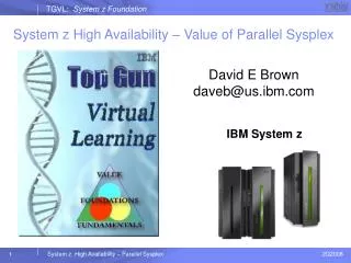
What else a Sysplex can do for YOU ! • Platform for continuous availability so that applications can be available 24 hours a day, 7 days a week, 365 days a year • Ability to do more work • Greater capacity • Improved ability to manage response time • Platform for further capacity and response time advances • Greater flexibility • Ability to mix levels of hardware and software • Ability to dynamically add systems • An easy path for incremental growth • Varied platforms for applications, including parallel, open, and client/server • Workload balancing
Sysplex Anatomy A sysplex can include the following software and hardware: 1. z/OS Products include the cross-system coupling facility (XCF) component, which enables authorized programs in a sysplex to communicate with programs on the same MVS system or other MVS systems and the global resource serialization component, which serializes sysplex resources. 2. Signaling paths between z/OS systems - There must be at least two operational signaling paths (one inbound and one outbound path) between each of the zOS systems - The signaling paths can be defined through: * Coupling facility list structures * ESCON or FICON channels operating in CTC mode * 3088 Multisystem Channel Communication Unit 3. Sysplex couple data set z/OS requires a DASD data set - Shared by all systems in the sysplex. - Sysplex couple data set, z/OS stores information related to the sysplex, systems, XCF groupsŦ, and their members. CF ŦAn XCF group is the set of related members that a multisystem application defines to XCF. A multisystem application can be an installation-defined program, an zOS component or subsystem, or a program product. However, you can define a single system sysplex that does not require a sysplex couple data set.
Sysplex Anatomy… continued 4. Common time reference When the sysplex consists of multiple zOS systems running two or more processors, zOS requires that the processors be connected to the same Sysplex Timer. - zOS uses the Sysplex Timer to synchronize TOD clocks across systems. - For a multisystem sysplex defined on a single processor (under PR/SM™ or VM) the SIMETRID parameter in the CLOCKxx parmlib member must specify the simulated Sysplex Timer identifier to synchronize timings for the zOS systems. TOD Clocks: In a configuration with more than one CP, each CP may have a separate TOD clock (as in the zOS’ Parallel Sysplex) or more than one CP may share the same clock. To assist in the synchronization of the TOD clocks in a multisystem sysplex, a new architected 128-bit extended time-of-day clock is available. The extended clock format was required to provide the improved resolution necessary for the faster z10 processors as they become available. The extended time-of-day architecture ensures that when an application in a multisystem sysplex environment requests a TOD value, XCF will always return a clock value that is unique across the sysplex, regardless of the number of systems in the sysplex.
Sysplex Coupling Facility - The glue for cross system data communication Within the Coupling Facility, storage is dynamically partitioned into structures. z/OS services manipulate data within the structures. Each of the following structures has a unique function: • Cache structure: Supplies a mechanism called buffer invalidation to ensure consistency of cached data. The cache structure can also be used as a high-speed buffer for storing shared data with common read/write access. • List structure: Enables authorized applications to share data that is organized in a set of lists, for implementing functions such as shared work queues and shared status information. • Lock structure: Supplies shared and exclusive locking capability for serialization of shared resources down to a very small unit of data. IBM illustrations and diagrams symbolizes a Coupling Facility (CF) using a triangle
Exploiters of the Coupling Facility (CF) • Authorized Applications • Information Management System Database (IMS DB) • Database 2 (DB2) • Virtual Storage Access Method
z/OS Resource Sharing Later configurations Earlier configurations
System z Sysplex Resource Sharing • This is not to be confused with application data sharing • This is sharing of physical system resources such as tape drives, catalogs, consoles • This exploitation is built into z/OS • Simplifies the management of the system
What is Parallel Sysplex • Builds on the strength of System z servers by linking up to 32 images to create the industry’s most powerful commercial processing clustered system • Every “cloned” application can run on every image • Hardware and software can be maintained non-disruptively • Innovative multi-system data-sharing technology • Direct concurrent read/write access to shared data from all processing nodes • No loss of data integrity • No performance hit • Transactions and queries can be distributed for parallel execution based on available capacity and not restricted to a single node
Applications " SAME " Applications • Parallel Sysplex • Loosely coupled multiprocessing • Hardware/software combination • Requires: • Data sharing • Locking • Cross-system workload dispatching • Synchronization of time for logging, etc. • High-speed system coupling • Hardware: • Coupling Facility • Integrated Cluster Bus and ISC to provide high-speed links to CF • Sysplex Timer – Time Of Day clock synchronization • Implemented in z/OS* and subsystems • Workload Manager in z/OS • Compatibility and exploitation in software subsystems, includingIMS*, VSAM*, RACF*, VTAM*, JES2*, etc. - Rolling Maintenance System and Application Code System Z9
Continuous availability • Within a parallel sysplex cluster, it is possible to construct an environment with no single point of failure • Peer instances can of a failing subsystem can take over recovery responsibility for resources held by the failing instance • Alternatively the failing subsystem can be automatically restarted on still healthy systems • In a parallel sysplex it is possible that the loss of a server may be transparent to the application and the server workload redistributed automatically with little performance degradation • Each system is still individual • Software upgrades can be rolled through one system at a time on a sensible timescale for the business
Applications in a Parallel Sysplex • Design goal of no application changes • Benefits • Scalability • Integration of older applications with new workloads such as web serving • With an existing sysplex there is very little infrastructure work required for a new application. The existing infrastructure may even be used without the need for a new server
Policy Based Implementation Note: The External Time Reference (ETR) used by the different systems
Sysplex - Works with a Policy • A policy is a set of rules and actions that systems in a sysplex are to follow when using certain zOS services. • A policy allows zOS to manage systems specific resources in compliance with your system and resource requirements, but with little operator intervention. • A policy can be set up to govern all systems in the sysplex or only selected. NOTE: You might need to define more than one policy to allow for varying workloads, configurations, or other installation requirements at different times. For example, you might need to define one policy for your prime shift operations and another policy for other times (end of month). • The following policies can be used to enhance systems management in a sysplex: - The coupling facility resource management (CFRM) policy allows you to define how zOS is to manage coupling facility resources. - The sysplex failure management (SFM) policy, allows you to define how MVS is to manage system failures, signaling connectivity failures, and PR/SM reconfiguration actions. - The workload management (WLM) policy allows you to define service goals for workloads. - The automatic restart management policy allows you to define how MVS is to manage automatic restarts of started tasks and batch jobs that are registered as elements of automatic restart management. - The system logger policy, (LOGR), allows you to define, update, or delete structure or log stream definitions. Although you can define more than one policy of each type (except for system logger) only one policy of each type can be active at a time. For system logger, there is only one LOGR policy in the sysplex.
Sysplex Timers use a new server timer protocol (STP) • The Server Time Protocol is a new server wide facility keeping all clocks synchronized • - There is no additional hardware required as in the previous type configuration.
Intelligent Resource Director (IRD) • Intelligent Resource Director is not actually a product or a system component; rather it is three separate but mutually supportive functions: • WLM LPAR CPU Management • - This provides a means to modify an LPAR weight to a higher value in order to move • logical CPUs to that LPAR which is missing its service level goal. • Dynamic Channel-path Management (DCM) • - Dynamic Channel-path Management is designed to dynamically adjust the channel • configuration in response to shifting workload patterns. • - DCM is implemented by exploiting functions in software components, such as • WLM, I/O, and Hardware Configuration. This supports DASD controller in • order to have the system automatically manage the number of I/O paths • available to Disk devices. • Channel Subsystem I/O Priority Queueing (CSS IOPQ) • - This feature prioritizes I/O out through the channel and uses the SAP engine to create a queue
Needs More Resources Needs More Resources Production B WAS CICS DB2 PRODUCTION A WAS CICS DB2 TESTING Batch (low priority) Linux Prioritizing Work Across Images in a Server – IRD PR/SM, IRD and WLM work together to ensure that the resources of the server are correctly balanced to enable work to complete within stated policy goals Coupling Facility 90 65 10 35 40 65 35 60 Weight Weight Weight Weight z/VM z/OS z/OS z/OS Intelligent Resource Director Intelligent Resource Director Processor Resource / Systems Manager Processor Resource / Systems Manager System z LPAR Cluster A System z LPAR Cluster B
z END Extra Slides
Display of the CF Command output SDSF ULOG CONSOLE KETTNER LINE 94 RESPONSES NOT SHOWN COMMAND INPUT ===> /D CF SCROLL ===> PAGE RESPONSE=SYSA IXL150I 09.32.33 DISPLAY CF 846 COUPLING FACILITY 002084.IBM.02.000000023A6A PARTITION: 0E CPCID: 00 CONTROL UNIT ID: FFFD NAMED CF1LPAR COUPLING FACILITY SPACE UTILIZATION ALLOCATED SPACE DUMP SPACE UTILIZATION STRUCTURES: 175872 KSTRUCTURE DUMP TABLES: 0 K DUMP SPACE: 5120 K TABLE COUNT: 0 FREE SPACE: 799488 K FREE DUMP SPACE: 5120 K TOTAL SPACE: 980480 K TOTAL DUMP SPACE: 5120 K MAX REQUESTED DUMP SPACE: 0 K VOLATILE: YES STORAGE INCREMENT SIZE: 256 K CFLEVEL: 14 CFCC RELEASE 14.00, SERVICE LEVEL 00.11 BUILT ON 11/03/2004 AT 14:40:00 COUPLING FACILITY HAS ONLY SHARED PROCESSORS CF REQUEST TIME ORDERING: REQUIRED AND ENABLED COUPLING FACILITY SPACE CONFIGURATION IN USE FREE TOTAL CONTROL SPACE: 180992 K 799488 K 980480 K NON-CONTROL SPACE: 0 K 0 K 0 K SENDER PATH PHYSICAL LOGICAL CHANNEL TYPE F1 ONLINE ONLINE ICP Storage and attachment info
Coupling Facility Summary Display Filter View Print Options Help ------------------------------------------------------------------------------- SDSF ULOG CONSOLE KETTNER LINE COMMAND ISSUED COMMAND INPUT ===> /D XCF,CF SCROLL ===> PAGE RESPONSE=SYSA IXC361I 09.59.09 DISPLAY XCF 850 CFNAME COUPLING FACILITY CF1LPAR 002084.IBM.02.000000023A6A PARTITION: 0E CPCID: 00 CF2LPAR 002084.IBM.02.000000023A6A PARTITION: 0F CPCID: 00 Displays information about all CFs that are in the Policy
Display Filter View Print Options Help ------------------------------------------------------------------------------- SDSF ULOG CONSOLE KETTNER LINE 56 RESPONSES NOT SHOWN COMMAND INPUT ===> SCROLL ===> PAGE RESPONSE=SYSA IXC357I 10.06.58 DISPLAY XCF 854 SYSTEM SYSA DATA INTERVAL OPNOTIFY MAXMSG CLEANUP RETRY CLASSLEN 85 90 1500 60 10 956 SSUM ACTION SSUM INTERVAL WEIGHT ISOLATE 60 10 MAX SUPPORTED CFLEVEL: 14 MAX SUPPORTED SYSTEM-MANAGED PROCESS LEVEL: 14 CF REQUEST TIME ORDERING FUNCTION: INSTALLED SYSTEM NODE DESCRIPTOR: 002084.IBM.02.000000023A6A PARTITION: 0A CPCID: 00 SYSTEM IDENTIFIER: 3A6A2084 0A00021A COUPLEXX PARMLIB MEMBER USED AT IPL: COUPLEZ6 SYSPLEX COUPLE DATA SETS PRIMARY DSN: SYS1.XCFSCDS.PRI VOLSER: XCFCD1 DEVN: 9005 FORMAT TOD MAXSYSTEM MAXGROUP(PEAK) MAXMEMBER(PEAK) 12/07/1998 14:46:41 8 80 (41) 351 (9) ALTERNATE DSN: SYS1.XCFSCDS.ALT VOLSER: XCFCD2 DEVN: 9015 /D XCF,COUPLE CF Dataset Information
Display currently defined XCF Groups Display Filter View Print Options Help ------------------------------------------------------------------------------ SDSF ULOG CONSOLE KETTNER LINE COMMAND ISSUED COMMAND INPUT ===> /D XCF,GROUP SCROLL ===> PAGE RESPONSE=SYSA IXC331I 10.14.41 DISPLAY XCF 856 GROUPS(SIZE): ATRRRS(4) COFVLFNO(4) DXRGROUP(3) EZBTCPCS(4) IDAVQUI0(4) IGWXSGIS(4) IRRXCF00(4) ISTCFS01(4) ISTXCF(4) IXCLO004(4) IXCLO005(4) IXCLO007(4) IXCLO019(3) SYSATB01(2) SYSATB02(2) SYSATB03(2) SYSATB04(2) SYSBPX(4) SYSDAE(5) SYSENF(4) SYSGRS(4) SYSGRS2(1) SYSIEFTS(4) SYSIGW00(4) SYSIGW01(4) SYSIGW02(4) SYSIGW03(4) SYSIKJBC(4) SYSIOS01(4) SYSJES(4) SYSMCS(9) SYSMCS2(6) SYSRMF(4) SYSTTRC(4) SYSWLM(4) WSCDBP0(4) WSC175(4)
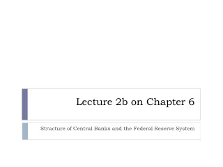
GDPS • A geographically dispersed parallel sysplex is the ultimate disaster recovery and continuous availability solution for a multi-site enterprise • Two sites up to 100 fiber kilometers apart may be connected for synchronous updates • Asynchronous techniques may be used over this distance
GDPS up to 100Km (62 miles) Time consistent data X
Summary • Reduce cost compared to previous offerings of comparable function and performance • Continuous availability even during change • Dynamic addition and change • Parallel sysplex builds on the strengths of the z/OS platform to bring even greater availability serviceability and reliability