Medium-Permittivity Ceramics
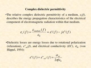
Medium-Permittivity Ceramics. 전기재료연구실 권 오 덕. Medium-Permittivity Ceramics. Medium-permittivity ceramics are widely used as Class Ⅰ dielectrics, and in order to be in this category they need to have low dissipation factors.

Medium-Permittivity Ceramics
E N D
Presentation Transcript
Medium-Permittivity Ceramics 전기재료연구실 권 오 덕
Medium-Permittivity Ceramics • Medium-permittivity ceramics are widely used as Class Ⅰ dielectrics, and in order to be in this category they need to have low dissipation factors. • For most purposes medium-permittivity ceramics have εr in the range 15 – 100. • There are three principal areas in which these dielectrics are applied. 1. High-power transmitter capacitors for the frequency range 0.5 - 50MHz for which the main requirement is low loss: a NTC of permittivity is tolerable since it limits the power through the unit when its temperature increases. 2. Stable capacitors for general electronic use: a stability better than ±1% is needed over the operational temperature and voltage ranges, and the frequency lies mainly in the 1kHz to 100MHz range.
Medium-Permittivity Ceramics 3. Microwave resonant cavities: these operate between 0.5 and 50GHz and require stabilities of better than ±0.05% over the operational temperature range with dissipation factors better than 2*10-4. • Medium-permittivity dielectrics are based on interlinked MO6 groups, where M is either a quadrivalent ion such as Ti, Zr, or Sn or a mixture of divalent, trivalent and pentavalent ions with an average charge of 4+. • The oxygen octahedra share corners, edges or faces in such a way that the O2- ions form a close-packed structure. • Sites in the O2- lattice may be occupied by divalent cations that lie in interstices between the MO6 octahedra, as in perovskite-type materials.
5.6.1 Rutile ceramic • Titania : three crystalline modification(anatase, brookite, rutile) => 800℃에서 anatase와 brookite는 rutile로 변환 • Fig.5.27 : rutile structure • Rutile is anisotropic, 상온에서εr = 170 : c 방향εr = 90 : a 방향다결정 세라믹은 온도계수가 -750M/K인 점에서 εr이 평균치를 보임 • Fig.5.28titania-based ceramicεr(ω,T)와 tanδ(ω,T) 특성
Rutile ceramic • Pure rutile : 상온에서 좋은 절연체임, 3.5~4.0eV범위내에서 filled O 2p valence band와 empty ti 3d conduction band사이에서 optical band gap을 가짐. Thermal energy(1.7~2.0eV)에서 valence에서 conduction band로 전자를 전환하는 semiconductivity를 가짐 • Fig.5.29 : typical conductivity data forhigh-purity titania ceramic(>99.95wt% TiO2) measured in oxygen at 1 atm • Fig.5.30 : 산소압과 온도의 함수rutile single crystal의 c방향 conductivity
Rutile ceramic • 저항감소는 산소결핍에 의한 것이며 Ti ion의 interstitial site로의 이동은 rutile 구조의 empty octahedral을 뜻함2OO + TiTi → O2(g) + TiI’’’’ + 4e` (5.18)The law of mass action leads to [TiI’’’’]n4 = KnpO2-1 (5.19)and since n ≒ 4[TiI’’’’ ] n = (4Kn)1/5pO2-1/5 (5.20)식(5.20) ⇒ 산소압 10-10 atm이하에서 1000℃의 conductivity의 측정 • Magneli phase : Non-stoichiometric phase is made up of stoichio -metric regions separated by a series of regularly spaced crystal shear planes (예 : TinO2n-1, n=15,16,17,18,19,20,22,29,31 etc)TiO1.95 => 사실상 Ti20O39 • Most compositions containing TiO2 show similar behaviour when fired in reducing atmospheres, so that sintering in air or oxygen is essential if they are to be used as low-loss dielectrics
5.6.2 Degradation in titanium-containing oxides • Degradation : 2가지 다른 조건에서 일어남 • 1. 상온, 5VDC이하, 25㎛박막유전체의 capacitor : 수명test중 급속한 저항 감쇠 ⇒ 복원 : -초기 level [by application of higher(10×) voltage] - minor mechanical disturbance* restored 이유 : (추측) silver has migrated in the form of a filament which results in a low-resistance path bridging the electrodes.* 전류증가는 Joule 열과 fusion에 의해 filament를 파괴함* Multilayer capacitor는 crack에 의한 구조적 결함을 지님. 습도 결함 • 2. 85℃이상, 0.5MV/m이상 degradation발생 : 급속한 전계, 온도 증가* rutile, barium titanate의 single crystal에서 저항 감쇠 ⇒ grain boundary effect • Degradation is accompanied by the movement of charged defects such as vacant oxygen sites behave as donors the region near the cathode becomes increasingly conductive, but the mechanism by which the resistance of the whole region between the electrodes falls is not clear
Degradation in titanium-containing oxides • Degradation은 적절한 치환물에 의해 늦춰질 수 있음 : donor ion 치환2mol.%초과 치환 Ti4+→Nb5+, Ba2+ → La3+, O2- → F- ⇒수명연장Donor ions reduce the concentration of oxygen vacancies, which are relatively mobile, and increase the concentration of cation vacancies.The latter have low mobilities at room temperature and, when combined with holes in the valence band, behave as acceptors. • Air-fired 유전체내에 1% level의 망간은 palliative로 활동* Mn4+ must be expected to act as an effective electron trap since it is readily converted into Mn3+* Mn3+ will result in a correspending concentration of oxygen vacancies. • 습기는 열화 촉진 : H20 + VO + O2- → 2OH-Hydroxyl ions are only slightly larger than oxygen ions so that their presence does not lead to any major lattice distortion. The protons can move through the oxygen lattice under a field, behaving similarly to oxygen vacancies.
5.6.3 High-power capacitors • High-power capacitors : values range up to 5000pF, frequency of operation ranges up to 50MHz, withstand 3kV and pass 150A • Table 5.5 Properties of dielectrics for transmitter capacitors 낮은 유전손실을 위해 순도높은 출발원료 및 불순물없는 제조공정 필요 • 전기적 에너지 낭비에 의한 유전체 발열 평균 비율 ⇒ [I and U : root mean square current, voltage]
High-power capacitors • Cf) 500kW unit(tanδ=2×10⁻⁴)은 열로써 100W 낭비(dissipate)를 갖음 이므로 ⇒ 표면공간의 노출로 unit의 heat가 제거된다면 주위의 상승온도∇T는 그러므로, 온도상승⇒유전율과 주파수 상승, 유전체 두께의 감소 ∇T로 캐패시터의 최대전력비율 을 정할 수 있으며, 최대전력에서 구동시 unit의 주파수 범위보다 높거나 낮은지 알 수 있다. • Power-handling capability limited by high reactance 1/ωC, Um* Low frequency f1(high reactance 1/ωC, voltage rating Um)* Above a frequency f2(low reactance, current rating Im)
High-power capacitors • Power dissipated by the electrodes ⇒[Re : electrode resistance] • Re is complicated by the ‘skin effect’, by which high-frequency currents are concentrated near the surface of a conductor*effect reason ⇒ 직류전류가 wire를 흐를때 전류밀도는 wire의 cross-section에 분포한다. The wire can be which has its associated magnetic induction. A central filament is linked with more flux than a filament running along the outer surface of the wire. 교류전류일때는 back e.m.f.는 표면보다 cross-section의 중심을 따르는 것이 더 크다. 결론적으로 길이에 따르는 전류밀도는 중심에서 바깥쪽(표면)을 향하는 방사상 형태로 증가한다. 사실상 전류밀도는 표면이하의 깊이에서 지수함수적으로 감소한다. The effect는 주파수와 비례적임. • Skin depth(δs) : the square root of the frequency에 반비례*1MHz일때 : 은(0.064mm), 구리(0.066mm), typical solid(0.19mm)표면 저항률 ρ’s : 은(2.5×10⁻⁷ΩHz-1/2), 구리(2.6×10⁻⁷ΩHz-1/2), solder(7.7×10⁻⁷ΩHz-1/2)
High-power capacitors • 전극의 전력손실 ⇒ Re=ρsl/w (l/w는 length-to-width retio), l≒w, Re≒ρs이므로 예) ρs=4×10⁻⁷ΩH-1/2인 500kW 500pF인 unit → 전력손실 0.1MHz(0.02W), 500MHz(7kW)/ • 1MHz이하에서 열발생이 유전손실의 주안점인 반면 1MHz 이상주파수에서는 급격한 손실의 비례(‘skin effect’)를 초래함(전극저항때문), 얇은 두께는 저항의 감소를 못만들지만 두꺼운 전극은 캐패시터로 열전이를 만들수 있음 • CaTiO3를 이용한 유전체 → 고유전율(140), 유전손실(2×10⁻⁴)TCC는 rutile-based dielectrics의 두배정도의 특성
5.6.4 Low-TCC low-loss capacitors • 공진주파수 : 온도범위 100K에서 0.1%이상의 내력, 온도계수 10MK-1의 0.1%이하의 내력을 유지해야 함 Small positive TCC을 가지는 manganese zinc ferrite pot-core inductor와 세라믹 캐패시터와 같은 NTCC를 가지는 inductance의 결합으로 10-100kHz를 가질수 있으며 공진조건으로부터ωO=(LC)-1/2 이며 온도로 편미분하면 • The parameters that contribute to the TCC can be indentified by first considering a rectangular parllel-plate capacitor with sides of length x and y and thickness z. C=εxy/z 온도로 편미분하면TCε is the temperature coefficient of permittivityαL is the linear expansion coefficient
Low-TCC low-loss capacitors • Capacitance의 온도변화원인 : capacitor지름변화, 유전율의 변화온도에 의한 유전율의 변화 : Clausius-Mosotti equation(온도편미분)εr ≥2이면V is the volume containing N polarizable unit Table 5.6 Temperature coefficient of permittivity of Class I dielectrics
Low-TCC low-loss capacitors • 지금까지는 유전체가 오염이 없는 이상적인 것으로 논의되었음. 실제로는 medium-permittivity Class I 유전체는 유전손실이 0.005이상임 • Volumetric efficiency 개선 방안 : high permittivity의 유전체와 small TCε의 유전체 결합예) BaTi3O7[εr=35, TCε=+35MK-1], TiO2[εr=100, TCε=-750MK-1] Fig.5.31 Temperature coefficient versus TiO2 content for BaTi3O7-TiO2 mixture
Low-TCC low-loss capacitors • Combination of high positive TCε with high ε and low loss are rare. The antiferroelectric compound PnZrO3 has εr=110 and TCε=1400 but tanδ=28×10-4. Sphene(CaSiTiO5) has εr=45, TCε=1200, tanδ=5×10⁻⁴. A combination of sphene and rutile gives a dielectric with zero TCε , εr=60-70, low loss. The crystal structure of sphene consists of chains of corner-sharing TiO6 octahedra interlinked by SiO4 tetrahedra by corner sharing. The Ti+4 ions are displaced from the centers of the octahedra by about 10pm but in opposite directions in alternate groups; therefore it is an antipolar structure. It is not antiferroelectric since there is no transition to a paraelectric state in which the Ti +4 ions have zero displacements.
5.6.5 Microwave ceramics • 위성통신, cellular radio 시스템의 발달로 초소형, 저가의 filter를 필요The solution to providing stable oscillators in the past lay in bulky coaxial and cavity resonators fabricated from the temperature-stable metal alloy Invar(불변강). The dielectric resonator(DR) offers a means of miniaturizing the device.DR : cylinder of ceramic of εr high for standing electromagnetic wave to be sustained within its volume because of reflection at the dielectric-air interface. Fig.5.32 Fields in a microwave resonance dielectric in the simplest standing-wave mode:(a) magnetic field; (b) electric field; (c) variation in EΦ and HZ with r at z=0, with reference to cylindrical coordinates (the z axis is perpendicular to the plane of the disc and the origin is at the disc center)
Microwave ceramics • The wavelength λ0, the diameter D of the cylinder λd≒D, resonance frequency f0=c/ λ0 (c : the free-space velocity)In a non-magnetic dielectric medium, the velocity v d=c/εr1/2 and so λd = λ0 /εr1/2. 그러므로TCf=-(0.5TCε + αL) eq(5.32)를 이용하여TCf=-0.5(TCC + αL) • 그러므로 TCε와 αL의 적절한 조절로 TCf=0(온도독립 공진주파수)를 얻을 수 있음 is the temperature coefficient of resonance frequency TCf Is the temperature coefficient of linear expansion αL is the temperature coefficient of permittivity TCε
Microwave ceramics • Fig.5.33 Frequency response of a microwave resonator * selectivity Q of the resonator is given by f0/∇f and under conditions where the energy losses are confined to the dielectric and not to effects such as radiation loss or surface condition, Q≒(tanδ)-1, where tanδ is the loss factor for the dielectric. • The requirements for DR ceramics are now clear.1. To miniaturize the resonator and to ensure that the electromagnetic energy is adequately confined to the resonator, εr must be large and is usually in the range 30<εr<100.2. To ensure stability against frequency drift with temperature, the temperature coefficient TCf must be contraolled, which implies control over TCε and αL3. To optimize frequency selectivity, Q≒(tanδ)-1 must be maximized and is usually greater than 1000.
Microwave ceramics • Micro device로서 TiO2가 고유전율(εr≒100), 낮은 손실(≒3×10⁻⁴)으로 부각됐지만, TCf(350MK-1)때문에 부적절 • Fig.5.34 : 4GHz에서 TCε측정 (a) varing titanium contents(CZT, SZT) (b)BSZ유전율범위(29-35), 유전손실범위( 3-11×10-4), Q 범위(1000-3000) • Fig.5.35 : [1400℃] The ZrxTiySnzO4(ZTS) system : the shaded area indicates the single-phase microwave ceramic field.
Microwave ceramics • Ba(Zn1/3Ta1/3)O3 : perovskite구조, high Q value, B site배열이 구조적 특성을 이해하는데 중요함예) 고온에서 재료를 annealing → increase order and Q(6000→14000) X-ray회절분석으로 알 수 있음, 불행히도 Zr의 증발과 grain growth함 이는 loss mechanism을 가짐을 설명 • Microwave ceramics 개선 : 출발재료 혼합, 하소, 혼합, 프레스(hot press), 소결의 조건에 의함, DRs have to be made to close dimensio-nal tolerances and this requires diamond machining as a final step.
Microwave ceramics • Fig.5.36 : Apparatus for measuring the microwave characteristics of dielectrics. Insert, detail showing specimen between conducting planes, and antennas. Dielectric cylinder(1.5cm in diameter and 6mm long). Two antennas radiate power into and extract power from the cavity; they are electromagnetically coupled with the resonant system as loosely as possible. f0로 εr결정, f0/∇f(3dB bandwidth)로 Q결정.The DR carries a fired-on silver coating. The Q of the DR ⇒ 1/Q = 1/Qd + 1/Qs + 1/QradQd : dielectric loss, values(5000정도)Qs : conducting surface loss, values(1000 at 900MHz)Qrad : radiated power loss, values(순수 silver 코팅이면 무시함) • Fig.5.37 : microwave circuits built onto ceramic substates and incorporating DRs.(a) metallized ceramic ‘engine block’ for 40MHz passband filter at 1.4GHz(b) 11.75GHz oscillator incorporating ceramic dielectric resonator together with various resonator pucks