Download
1 / 60
610 likes | 902 Views
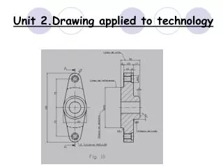
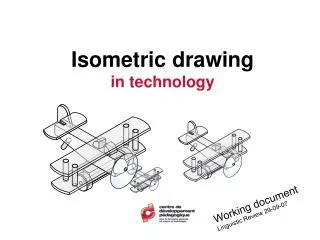
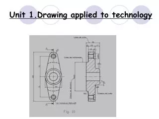
Unit 1.Drawing applied to technology. Unit 1.Drawing applied to technology. What are we going to see in this unit? 1.1 Drawing materials and instruments 1.2 Drafts and sketches 1.3 Drafting scale 1.4 Diedric system 1.5 Marking and standardizing 1.6 Perspective systems.

E N D
Unit 1.Drawing applied to technology • What are we going to see in this unit? • 1.1 Drawing materials and instruments • 1.2 Drafts and sketches • 1.3 Drafting scale • 1.4 Diedric system • 1.5 Marking and standardizing • 1.6 Perspective systems
1.1 Drawing materials and instruments • Paper • Paper is made of cellulose that is obtained from trees • The paper size that we use is A4 . It is the result of dividing 1 m2 (A0) four times by half the longest side.
1.1 DRAWING TOOLS THE RULER It is a precision tool that makes it possible to measure and to transfer a distance. TRIANGULAR SET SQUARE A set square is a tool for drawing perpendicular (vertical) and parallel lines and for obtaining angles. There are 2 types of trianglular set squares A 45 degree A 60 degree
1.1 Drawing materials and instruments How to draw vertical and parallel lines with the set square Vertical: Parallel: Activity: Draw the set squares in your notebook as you can see them in both positions
1.1 Drawing materials and instruments Drawing angles: we can get 15º, 30º, 45º, 60º, 75º, 90º, 120º, 135º…angles combining the 30º, 45º , 60º and the 90º angles from the set squares You don't have to copy them because you can find them in your text book on page 25
1.1 Drawing materials and instruments Solution Drawing angles exercise: you have to obtain, 45º, 75º, 90º, 120º angles combining the set squares
1.1 DRAFT AND SKETCH • DRAFT: Itis a free hand drawing (just with a pencil). We show an idea or object without totally defining it. Page 41
1.1 DRAFT AND SKETCH • ATTENTION! • A DRAFT IS NOT A BAD DRAWING AND A SKETCH IS NOT A GOOD DRAWING !!!!!!
1.1 DRAFT AND SKETCH The sketch: Itis a free hand drawing too, but it includes the measures, therefore it shows the precise size and a shape similar to the final drawing. measure Page 41
1.3 Drafting scale • We define scale as the relation between the drawing size and the real object A model uses a reduction scale
1.3 Drafting scale 1:2 The Drawing size The Real size Page 38
1:1200 1cm drawing 1200 reality Page 38 1.3 Drafting scale 1 cm measured on the drawing is equivalent to 1200cm in reality
1.3 Drafting scale • Scale types: • Reduction scale: it is used to represent big objects, so they can be drawn on paper • We usually use: 1:2 1:5 1:10… In this example we have reduced 1000 times the real size of the tree 1:1000 Real Real Real drawn
2:1 2:1 1.3 Drafting scale • Enlargement scale: it is used to represent small objects so we can see them on paper • It is used: 2:1 5:1 10:1 … In this example the drawing is two times the real object Safety pin Real Drawing
1cm 10cm 1.3 Drafting scale • An example of scale application • Let’s draw a pencil that is 10cm high and 1cm wide using different scales: 2:1, 1:2, 1:4
1.3 Drafting scale 2:1 Scale 2:1 Real
1.3 Drafting scale 2:1 Scale 1:2 Real 1:2
1.3 Drafting scale 2:1 2:1 2:1 Scale 1:4 Real Real Real Real 1:2 1:2 1:2 1:2 1:4
1.3 Drafting scale Scale exercise Using an electronic microscope we can see a virus that is 1,5pm. This picture is 6 cm long, do you know the scale used to draw it?
1.3 Drafting scale Scale ???:1
1.4 Diedric system The diedric system represents the objects using a perpendicular projection on a plane
1.4 Diedric system The projection or VIEW consists of drawing just what we see when we are perpendicular to the object and to the plane Page 28
1.4 Diedric system • Insert video
1.4 Diedric system • Insert video
Floor view Profile view Front view Profile view Front view Floor view 1.4 Diedric system • To define an object we only need 3 views, floor, front and profile: • Floor view: from the top of the object • Front view: facing the object • Profile view: from the side
front Left profile Right profile front floor floor 1.4 Diedric system • Diedric Rules • The front is usually indicated with an arrow • The views distribution • The front is always on top of the floor • The profile is situated the other way around, that is, the left profile is situated on the right
1.4 Diedric system • Remember: • The same height: the object has the same height on the floor and on the profile views • The same width: on the front and on the floor views • The same depth: on the floor and on the profile views
1.4 Diedric system • Exercise: Draw the front, left profile and floor views of the class chair. This chair is 80 cm high, 40 cm wide and 40 cm deep. Use the proper scale
1.4 Diedric system Where do we have to be situated to see these objects like circles?
1.4 Diedric systemExercise 11: Complete the views of the following objects Page 31
1.4 Diedric system • Non visible lines: when we know there is a hidden line we have to draw it using a discontinuous line hidden line
1.4 Diedric system Activity: draw the front, floor and left profile views of this figure coloring each face in one color. Apply a proper scale 30cm 20cm 100cm 100cm
1.4 Diedric system • Exercice: draw the right profile, front and floor views of these objects 100cm
1.5 Marking and standardizing • The standardizing is the group of rules that define objects in technical drawing.
1.5 Marking and standardizing Using a standard language we can define the size, materials and properties of an object so that anyone can read it
1.5 Marking and standardizing • There are several elements used to draw a object, but we are going to see only the most relevant: • Paper For paper size we use the DIN rule: A0,A1,A2…
1.5 Marking and standardizing • 2.- Lines • The lines are: • Thick continuous lines: are used to outline objects • Thick discontinuous lines: indicate hidden lines • Thin continuous lines: are used for auxiliary measures and reference lines. • Dots and thin discontinuous lines: indicate a circumference or cylinder axis
1.5 Marking and standardizing Circumference axis line Auxuliary Line Measure Measure line Reference line
1.5 Marking and standardizing Marking : indicating the real dimensions above the object
1.5 Marking and standardizing. Marking follows some rules • The measure lines: • We place them parallel to the edge and slightly separated • They are limited by the auxiliary lines • The arrows are thin and elongated, they go from one side to the other
1.5 Marking and standardizing • Auxiliary lines • We place them perpendicular to the measure lines • They cross the measure line a little bit • They never cut the measure line
1.5 Marking and standardizing • The measures: • We indicate the real measure in milimetres, but “mm” is never written • They are placed above the measure line, never under it • We only use the extrictly necessary measures
Measure line ends Arrow: ends in a aux. Line Line: ends in a measure line Dot: ends in a line object Measures position
1.5 Marking and standardizing • Activity: draw these views indicating which rules are broken Wrong Correct
Exercice: Make a file of this object, drawing its views including all measures, AND SCALE Assembled size Width: 79 cm Wood widht: 5 cmDepth: 39 cmHeight: 79 cmMax load/shelf: 13 kg
1.6 Perspective systems Which one of these objects is a cube?
1.6 Perspective systems They are all cubes, but drawn with different perspectives
1.6 Perspective systems But, what is a perspective? It is an approximate representation, on a flat surface (such as paper), of an image as it is perceived by the eye.