Download
1 / 30
500 likes | 988 Views
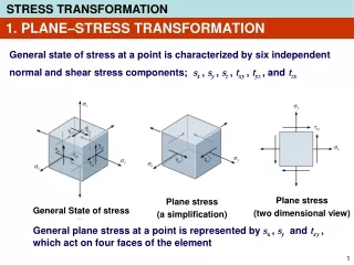
Plane stress (two dimensional view). Plane stress (a simplification). General State of stress. 1. PLANE–STRESS TRANSFORMATION. General state of stress at a point is characterized by six independent normal and shear stress components; s x , s y , s z , t xy , t yz , and t zx.

E N D
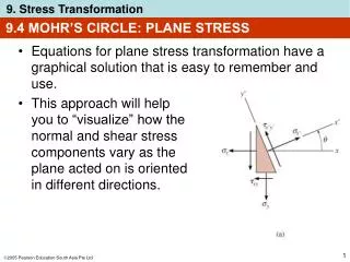
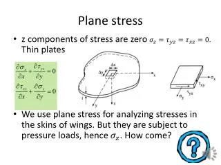
Plane stress (two dimensional view) Plane stress (a simplification) General State of stress 1. PLANE–STRESS TRANSFORMATION General state of stress at a point is characterized by six independent normal and shear stress components;sx, sy, sz, txy, tyz, and tzx General plane stress at a point is represented by sx, syand txy, which act on four faces of the element
y sy txy x sx y’ sy’ tx’y’ x’ sx’ q 1. PLANE–STRESS TRANSFORMATION If we rotate the element of the point in different orientation, we will have different values of the stresses The stresses are now sx’ , sy’ and tx’y’ It is said that the stress components can be transformed from one orientation of an element to the element having a different orientation
45o Failure of a brittle material in torsion Failure of a brittle material in tension 1. PLANE–STRESS TRANSFORMATION Failure of a brittle material will occur when the maximum normal stress in the material reaches a limiting value that is equal to the ultimate normal stress
+sy y +txy +sx x 2. GENERAL EQUATION OF PLANE–STRESS TRANSFORMATION Sign Convention A normal or shear stress component is positive provided it acts in the positive coordinate direction on the positive face of the element, or it acts in the negative coordinate direction on the negative face of the element
y y’ y x’ +q x x 2. GENERAL EQUATION OF PLANE–STRESS TRANSFORMATION The orientation of the inclined plane, on which the normal and shear stress components are to be determined, will be defined using the angle q The angle qis measured from the positive x to the positive x’
(b) (a) 2. GENERAL EQUATION OF PLANE–STRESS TRANSFORMATION The element in Fig.(a) is sectioned along the inclined plane and the segment shown in Fig.(b) is isolated. Assuming the sectioned area is DA, then the horizontal and vertical faces of the segment have an area of DA sinq and DA cosq, respectively
We get 2. GENERAL EQUATION OF PLANE–STRESS TRANSFORMATION Resulting free-body diagram The unknown normal and shear stress components in the inclined plane, sx’ and tx’y’, can be determined from the equations of force equilibrium Fy’= 0 Fx’= 0
sy’ tx’y’ sx’ 2. GENERAL EQUATION OF PLANE–STRESS TRANSFORMATION Three stress components, sx’ , sy’ and tx’y’ , oriented along the x’, y’ axes
3. PRINCIPAL STRESSES & MAX.IN-PLANE SHEAR STRESSES To determine the maximum and minimum normal stress, we must differentiate equation of sx’ with respect to q and set the result equal to zero. This gives Solving this equation, we obtain the orientation q = qp of the planes of maximum and minimum normal stress
9-3 PRINCIPAL STRESSES & MAX.IN-PLANE SHEAR STRESSES The solution has two roots; qp1 and qp2 2qp2 = 2qp1 + 180o Based on the equation of tan2qp above, we can construct two shaded triangles as shown in the figure
3. PRINCIPAL STRESSES & MAX.IN-PLANE SHEAR STRESSES sin 2qp2 = – sin 2qp1 cos 2qp2 = – cos 2qp1 The equation of the maximum/minimum normal stresses can be found by substituting the above equations into sx’
In-plane principal stresses 3. PRINCIPAL STRESSES & MAX.IN-PLANE SHEAR STRESSES Principal stresses = Maximum and minimum normal stress
3. PRINCIPAL STRESSES & MAX.IN-PLANE SHEAR STRESSES Depending upon the sign chosen, this result gives the maximum or minimum in-plane normal stress acting at a point, where s1s2. This particular set of values, s1 and s2, are called the in-plane principal stresses, and the corresponding planes on which they are act are called the principal planes of stress Furthermore, if the trigonometric relations for qp1 and qp2 are substituted into equation of tx’y’, it can be seen that tx’y’= 0; that is, no shear stress acts on the principal planes
3. PRINCIPAL STRESSES & MAX.IN-PLANE SHEAR STRESSES Maximum In-Plane Shear Stress Similarly, to get the maximum shear stress, we must differentiate equation of tx’y’ with respect to q and set the result equal to zero. This gives The solution has two roots;qs1 and qs2 2qs2 = 2qs1 + 180o
3. PRINCIPAL STRESSES & MAX.IN-PLANE SHEAR STRESSES The maximum shear stress can be found by taking the trigonometric values of sin 2qs and cos 2qs from the figure and substituting them into equation of tx’y’ . The result is (9-7) Substituting the values for sin 2qs and cos 2qs into equation of sx’, we see that there is also a normal stress on the planes of maximum in-plane shear stress. We get
4. MOHR’S CIRCLE PLANE STRESS We rewrite the stress component sx’andtx’y’as follows Squaring each equation and adding the equation together can eliminate the parameter q. The result is
4. MOHR’S CIRCLE PLANE STRESS Since sx , syandtxyare known constants, the above equation can be written in a more compact form as
s txy sx t 4. MOHR’S CIRCLE PLANE STRESS This equation represents a circle having a radius R and center on saxis at point C(savg, 0) as shown in the Figure This circle is called MOHR’S CIRCLE
y sy txy x sx t savg s C txy A sx 4. MOHR’S CIRCLE PLANE STRESS Procedure how to draw and use Mohr’s circle A stress state of a point which all stresses sx , syandtxy are positive (just for example) CONSTRUCTION OF MOHR’S CIRCLE • Establish a coordinate system; • s-t axis • Plot the center of the Mohr’s circle • C(savg, 0) on s axis savg = (sx + sy)/2 • Plot the reference point A(sx,txy). • This represents q = 0 • Connect point A with the center C, and • CAbecomes the radius of the circle • Sketch the circle
s1 E tmax qs1 B D qp1 s2 tmax F t savg s C txy A sx 4. MOHR’S CIRCLE PLANE STRESS ANALYSIS OF MOHR’S CIRCLE Principal Stresses s1and s2 • Point B: s1 • Point D: s2 Orientation of principal plane, qp1 tmax=CE = CF Maximum In-Plane Shear Stress: Orientation of maximum in-plane shear stress, qs1
5. STRESS IN SHAFT DUE TO COMBINED LOADINGS • Occasionally, circular shafts are subjected to the combined • effects of torsion and axial load, or torsion and bending, or in fact • the combined effects of torsion, axial load, and bending load. • Provided the material remains linear elastic, and is only subjected • to small deformation, and then we can use the principle of • superposition to obtain the resultant stress in the shaft due to the • combined loadings. • The principal stress can then be determined using either the stress transformation equations or Mohr’s circle
(a) (a) (b) EXAMPLE 1 Stress in Shafts Due to Axial Load and Torsion An axial force of 900 N and a torque of 2.50 N.m are applied to the shaft as shown in the figure. If the shaft has a diameter of 40 mm, determine the principal stresses at a point P on its surface. Internal Loadings The internal loadings consist of the torque and the axial load is shown in Fig.(b)
(a) 198.9 kPa (b) EXAMPLE 1 Stress Components • Due to axial load • Due to torsional load
= – 29o EXAMPLE 1 The state of stress at point P is defined by these two stress components Principal Stresses: We get s1 = 767.8 kPa s2 = – 51.6 kPa The orientation of the principal plane: qp = 14.5O
T y x z EXAMPLE 2 Stress in Shaft due to Bending Load and Torsion A shaft has a diameter of 4 cm. The cutting section shows in the figure is subjected to a bending moment of2 kNm and a torque of 2.5 kNm. • Determine: • The critical point of the section • The stress state of the critical point. • The principal stresses and its orientation
T A y x z EXAMPLE 2 Analysis to identify the critical point • Due to the torque T Maximum shear stresses occur at the peripheral of the section. • Due to the bending moment M Maximum tensile stress occurs at the bottom point (A) of the section. Conclusion: the bottom point (A) is the critical point
198.9 kPa 318.3 kPa T A y x z EXAMPLE 2 Stress components at point A • Due to the torque T 198.9 kPa • Due to the bending moment M 318.3 kPa Stress state at critical point A txy = 198.9 kPa sx = 318.3 kPa
198.9 kPa 318.3 kPa s2 s1 25.65o = 51.33o EXAMPLE 2 Principal stresses We get s1 = 413.9 kPa s2 = – 95.6 kPa The orientation of the principal plane: qp = 25.65O
EXAMPLE 3 Stress in Shafts Due to Axial Load, Bending Load and Torsion A shaft has a diameter of 4 cm. The cutting section shows in the figure is subjected to a compressive force of 2500 N, a bending moment of800 Nm and a torque of 1500 Nm. Determine: 1. The stress state of point A. 2. The principal stresses and its orientation
t s EXAMPLE 3 Analysis of the stress components at point A • Due to comprsv load: • Due to torsional load: • Due to bending load: (compressive stress) Stress state at point A Shear stress: t = tA Normal stress: s = sA’ + sA” SOLVE THIS PROBLEM!!!